
Assortment of Siren Circuits

The design of the first siren circuit, which emulates the sound of a British police car, incorporates two 555 timer integrated circuits (ICs) configured in astable mode. The astable configuration allows the circuit to generate a continuous square wave output, which can be adjusted in frequency to create the desired siren effect.
In this circuit, the first 555 timer is responsible for generating a base frequency, while the second 555 timer modulates this frequency to produce a varying pitch characteristic of a police siren. The frequencies can be adjusted by changing the resistor and capacitor values connected to each timer. For instance, using a potentiometer in series with a resistor can provide a variable frequency output, allowing for fine-tuning of the siren sound.
The output from the second 555 timer is typically fed into a small audio amplifier to drive a speaker, ensuring that the siren sound is audible. An additional feature may include a LED indicator that flashes in sync with the siren sound, enhancing the visual effect of the circuit.
Power supply considerations are essential, with a typical configuration using a 9V battery or a regulated power supply to ensure stable operation of the timers. Proper decoupling capacitors should be placed across the power supply pins of the 555 timers to minimize noise and ensure reliable performance.
In summary, the first siren circuit design effectively simulates the sound of a British police car using two 555 timers, with attention to frequency modulation, output amplification, and power supply stability.Assortment of Siren Circuits. This month I am making 3 different types of siren circuits based on the 555 timer. The first circuit simulates the siren of a British police car. It uses two. 🔗 External reference
Related Circuits
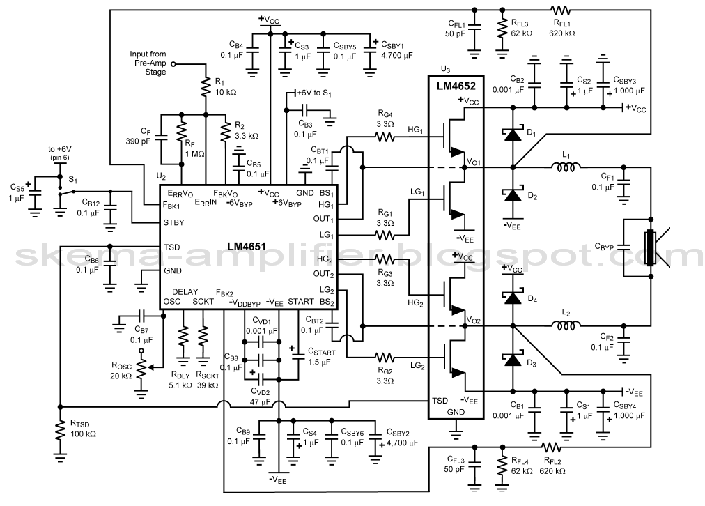
The LA4440 is a two-channel audio power amplifier integrated circuit (IC) designed for stereo and bridge amplifier applications. In dual mode, it provides an output of 6 watts per channel, while in bridge mode, it can deliver up to...

This is a single-zone alarm system featuring independently adjustable Exit, Entry, and Siren Cut-Off timers. It is compatible with standard normally-closed input devices such as magnetic-reed contacts, foil tape, and passive infrared sensors (PIRs). A mains power supply can...
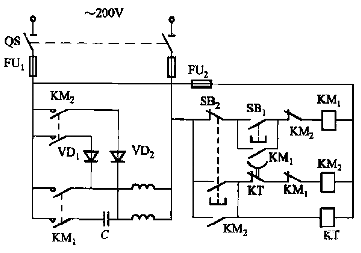
The circuit depicted in Figure 3-150 involves a contactor (KM1) that releases when the system is shut down. The contactor KM2 is energized, allowing a 220V AC power supply to flow through diodes VD1 and VD2, which serve as...
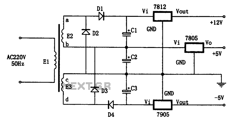
The circuit illustrated in the figure represents a specialized power supply configuration. It is straightforward in design and can be constructed using two identical secondary windings to generate three distinct DC voltage outputs: +5V, -5V, and +12V. The circuit...
Maxim has introduced a series of five integrated oscillator building blocks in the MAX260x series, covering a frequency range of 45 to 650 MHz. The MAX2606 is designed for the VHF band, allowing frequency variation of approximately ±3 MHz...
The first integrated circuit (IC) on the left is configured to operate at a frequency of approximately 1 Hz. A 47 µF capacitor is charged and discharged in a periodic manner, resulting in a gradual increase and decrease of...