
Police Siren

The described circuit functions as a simple oscillator, utilizing the properties of the capacitor and the integrated circuit to generate a square wave signal at a frequency of 1 Hz. The IC is likely configured in an astable multivibrator mode, where it continuously switches between its high and low states. The charging and discharging of the 47 µF capacitor is central to this operation.
As the capacitor charges through a resistor connected to the output of the IC, the voltage across the capacitor rises until it reaches a threshold level that triggers the IC to switch states. This transition causes the output to go low, allowing the capacitor to discharge through another resistor. The discharge process lowers the voltage across the capacitor until it reaches a lower threshold, prompting the IC to switch back to its high state, thus restarting the cycle.
The choice of a 47 µF capacitor suggests a design consideration for the timing characteristics of the circuit. The time constant, determined by the resistance in series with the capacitor and the capacitance value, dictates the rate of charging and discharging. This is calculated using the formula T = R x C, where T is the time period, R is the resistance, and C is the capacitance. For a frequency of approximately 1 Hz, the values of the resistors must be selected carefully to ensure that the total time period matches the desired frequency.
This circuit can be utilized in various applications, such as in timers, flashing LED indicators, or as a clock pulse generator for other digital circuits. The simplicity of the design allows for easy modifications, such as changing the frequency by adjusting the capacitor value or the resistors used in the charging and discharging paths. Proper consideration of component tolerances and voltage ratings is essential for ensuring reliable operation over time.The first IC (left) is wired to work around 1Hz. The 47uF capacitor is charged and discharged periodically and the voltage across it gradually increases and decreases periodically. 🔗 External reference
Related Circuits
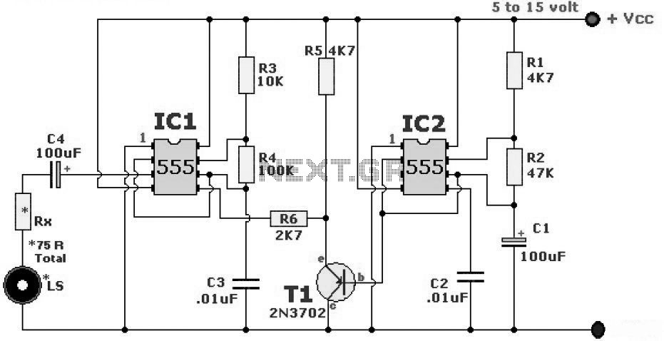
The wailing alarm circuit diagram includes the following component parts: R1 and R5 are 4.7 kΩ resistors, R2 is a 47 kΩ resistor, R3 is a 10 kΩ resistor, R4 is a 100 kΩ resistor, and Rx is specified...
The one-shot and decay functions could be added to create an ideal phasor gun sound. To design a circuit that generates a phasor gun sound using one-shot and decay functions, the following components and configuration can be utilized. The one-shot...
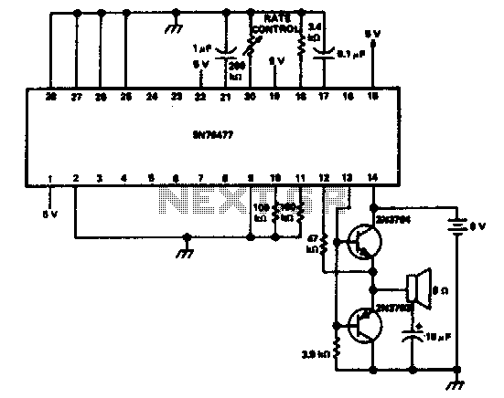
This circuit features a two-tone siren integrated within a single IC. It is designed for children's entertainment and can be installed on bicycles, car battery chargers, and other applications. The two-tone siren circuit utilizes a single integrated circuit (IC) to...

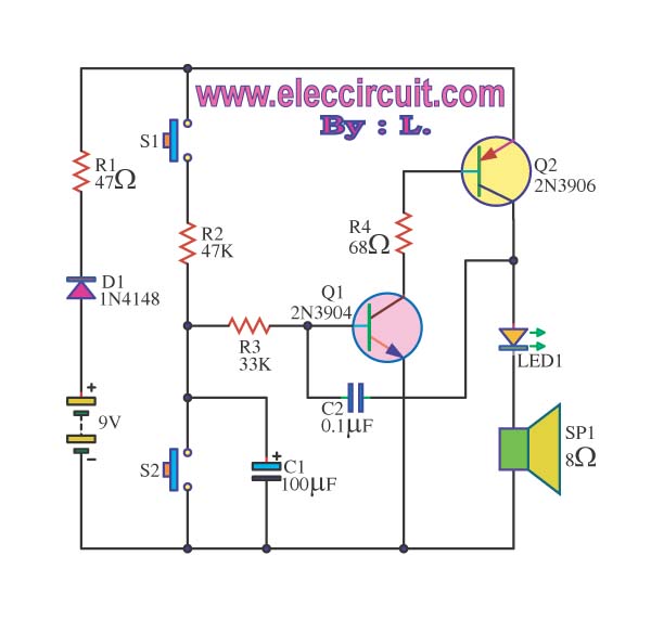
This is a siren sound generator circuit that is cost-effective and capable of producing simple sound patterns. The circuit utilizes IC1, which is a CD4011 (Digital NAND Gate), and IC2 is... The siren sound generator circuit is designed to produce...
The siren circuit plays a crucial role in various alarm systems, including emergency alerts, burglar alarms, fire alarm circuits, timers, and sensor controls. Without these circuits, it would be impossible to recognize the intended functionality. The operation of the...
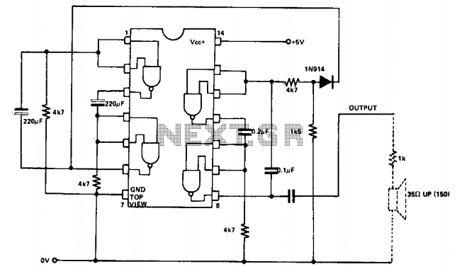
Two NAND gates are utilized in the oscillator configuration, while two additional NAND gates serve as control elements. To modify the two-tone speed, the 220 µF capacitors can be replaced with larger values for slower operation. For frequency adjustments...