
Astable circuits produce pulses using 555

The SE555/NE555 timer is a versatile integrated circuit widely used in various applications such as timers, pulse generation, and oscillators. The device operates in different modes, including monostable, astable, and bistable configurations.
In the monostable mode, the timer produces a single output pulse in response to a trigger signal. The duration of the output pulse is determined by an external resistor and capacitor connected to the timer. The time period can be calculated using the formula: T = 1.1 * R1 * C1, where T is the pulse duration, R1 is the resistance in ohms, and C1 is the capacitance in farads.
In astable mode, the SE555 timer operates as an oscillator, generating a continuous square wave output. The frequency and duty cycle of the output waveform can be adjusted by varying the values of two external resistors (R1 and R2) and a capacitor (C1). The frequency can be calculated using the formula: f = 1.44 / ((R1 + 2 * R2) * C1), while the duty cycle can be expressed as: Duty Cycle = (R2 / (R1 + 2 * R2)) * 100%.
The bistable mode allows the SE555 to act as a flip-flop, where the output state can be toggled between high and low states by applying trigger signals to the appropriate pins.
The device features a reset pin (Pin 4), which can be used to terminate the timing cycle prematurely, and an output pin (Pin 3) that provides the timed output signal. The SE555 timer is capable of sourcing or sinking up to 200 mA of current, making it suitable for driving various loads directly.
Overall, the SE555/NE555 timer is a robust and reliable component that is integral to many electronic designs, providing precise timing and waveform generation capabilities.First introduced by the Signetics Corporation as the SE555/NE555 about 1971. Pin connections and functions: (See schematic below for basic circuits) Pin 1 (Ground) - The ground (or common) pin is the most-negative supply potential of the device, which is normally connected to circuit common when operated from positive supply voltages. Pin 2 (Trigger) - This pin is the input which causes the output to go high and begin the timing cycle.
Triggering occurs when the trigger input moves from a voltag. 🔗 External reference
Related Circuits
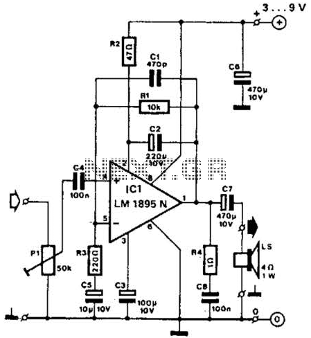
This amplifier operates with supply voltages ranging from 3 V to 9 V and can deliver an output power ranging from 100 mW to 1 W into a 4-ohm load. The bandwidth is approximately 20 kHz at a 3...
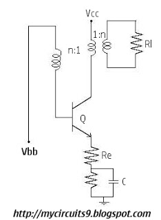
Initially, there is a voltage Vc on capacitor C1 that is greater than Vbb - Vg, where Vg is the cutoff base-emitter voltage and g represents Gamma. Consequently, the transistor is in the off state, and capacitor C1 discharges...
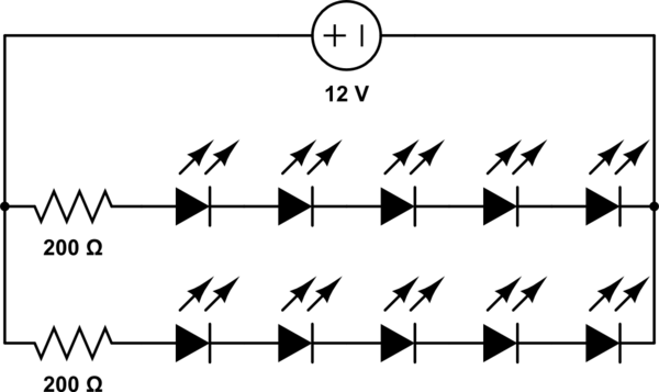
A 12V power supply is available, and there is a need to power LEDs with a forward voltage of 2V. It is questioned whether only six LEDs can be powered or if the cathode of one LED can be...
In this project, an embedded system is designed for tracking and positioning vehicles using the Global Positioning System (GPS) and Global System for Mobile Communications (GSM). The AT89S52 microcontroller interfaces with various hardware peripherals. The system continuously monitors a...
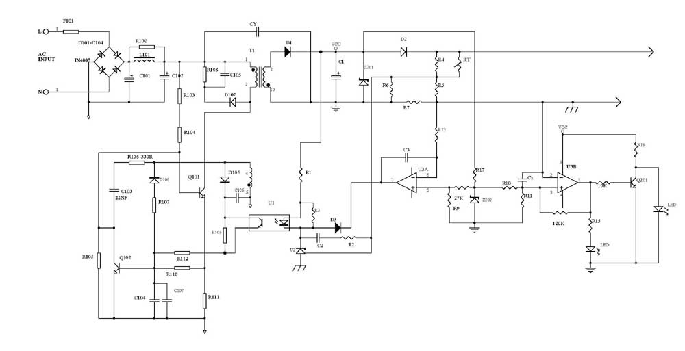
Several schematic drawings of battery charger circuits are provided. These circuits cover 5W to 200W for NiCd, NiMH, Lead-Acid, Li-Ion/Polymer, and LiFePO4 battery packs. The charger circuit files aim to assist users in selecting the appropriate chargers and to...
This page shows some methods of track routing control for Stall-Motor type switch machines. The principle method uses a 2 Pole - Multi Position rotary switch while an alternate uses optoisolators and transistors to select the routes. The last...