
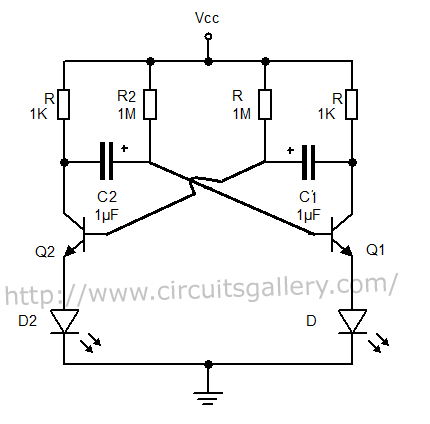
Astable Multivibrator with 2 Transistors

This circuit employs two NPN transistors, typically the MPS2222, to create a simple oscillator or switching circuit. The configuration allows for the generation of square wave signals, effectively transitioning between HIGH and LOW states.
The circuit operates with a power supply of 9V, ensuring the Emitter-Base Voltage remains below the maximum threshold of 5V for reliable operation. The use of capacitors C1 and C2 in conjunction with resistors R1 and R2 is critical for establishing the timing characteristics of the circuit. The time constant, defined as \( t = 0.693 RC \), is pivotal in determining the duration of the HIGH and LOW states, where R represents the resistance in ohms and C represents the capacitance in farads.
The output of the circuit is indicated by two LEDs, which serve as visual indicators of the state of the circuit. Current limiting resistors are incorporated to prevent excessive current from flowing through the LEDs, thereby protecting them from damage. The design allows for the output to toggle between HIGH and LOW, creating a pulsing effect that can be utilized in various applications, such as blinking lights or signal generation.
The frequency of the output signal can be calculated based on the time period derived from the time constant. The transition frequency from HIGH to LOW can be computed using the formula \( f = \frac{1}{T} \), where \( T \) is the period of the oscillation. This frequency is determined by the values of the resistors and capacitors used in the circuit, allowing for customization based on desired operational parameters.
Overall, this circuit exemplifies a fundamental application of transistor switching, providing a basis for more complex electronic designs.This circuit is basically simple and easy to build, it uses two transistors as active components and a few passive components like resistors, capacitors and two LEDs. The circuit makes use of the MPS2222 transistor. You can use any NPN type transistor as the basis of your circuit provided that, the transistors Emitter-Base Voltage is less than 12V and has a maximum value of 5V.
This is to ensure that the circuit will work under a 9V Battery power supply. The circuit generates a H(HIGH) to L(LOW) level and L to H level transition. This H to L or L to H transition is generated by capacitors C1 and C2 and resistors R1 and R2, the LEDs acts as output loads to the circuit and the other resistors serves as current limiting resistors for the protection of the LED diodes. Taking one-half of the circuit we can calculate the time period which makes the high or low transitions for a single transistor.
Thus, the time constant can be calculated as: t = 0.693 RC The transition frequency from HIGH to LOW state can be computed as: 🔗 External reference
Related Circuits
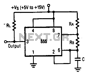
This astable multivibrator will trigger itself and operate continuously. The external capacitor charges through resistors RA and RB and discharges solely through resistor R8. Consequently, the duty cycle is determined by the ratio of these two resistors, allowing the...
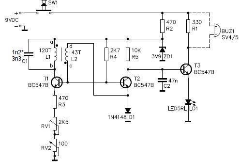
This metal detector circuit project is a simple design based on common electronic components. It utilizes transistors to provide a visual indication through an LED and an acoustic signal to alert users when metal is detected. To calibrate the...
The output can also be taken from the collector terminals of the transistors, as illustrated in the circuit below. To understand the operation of the circuit, it is recommended to read about how a transistor functions as a switch. In...
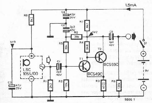
This electret microphone amplifier is constructed using standard electronic components. It is designed to work with an electret microphone capsule, although it can also accommodate a dynamic microphone that has low resistance. The circuit operates with a supply voltage...
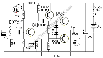
The output of this circuit is push-pull and consumes less than 3 mA (with no signal) but drives the earpiece to a very loud level when audio is detected. This circuit operates in a push-pull configuration, which allows it to...
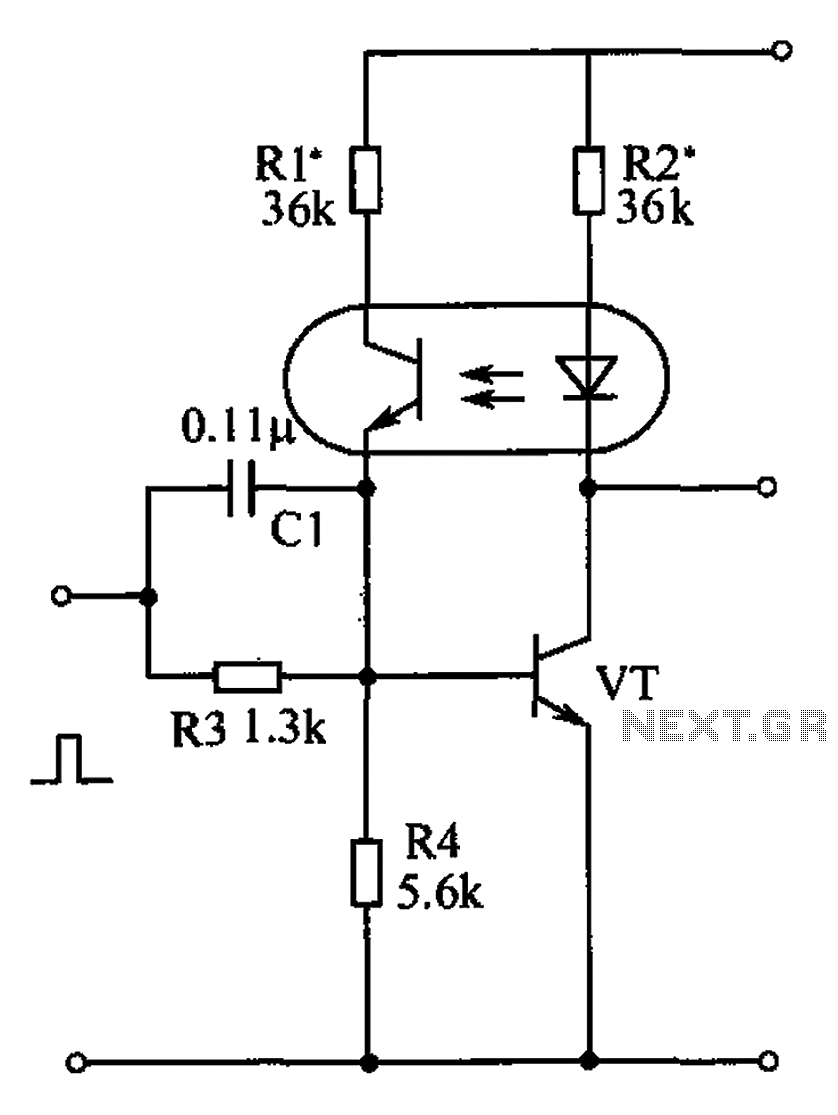
The bistable circuit and optocoupler transistor operate as illustrated in the accompanying figure. Initially, when the supply voltage is applied, the transistor VT is in the off state, resulting in a high output potential. Upon receiving a forward pulse...