
ASUS Eee Car Charger

The circuit design for the custom car charger incorporates several key components and considerations to ensure reliable operation and efficiency. The LM2576 IC serves as the heart of the charger, allowing for adjustable voltage output while managing the current requirements of the ASUS Eee. The inductor, essential for the switching regulator's operation, is chosen for its compatibility with the LM2576, ensuring optimal performance. The circuit layout must be carefully designed to minimize electromagnetic interference and ensure stable operation under varying load conditions.
The low voltage cut-out feature is critical for protecting both the charger and the vehicle's battery. By monitoring the input voltage and shutting down the regulator at a predetermined threshold, this design mitigates the risk of battery drain, which is particularly important in automotive applications. The use of a Zener diode in conjunction with the BC337 transistor provides a simple yet effective means of implementing this safety feature.
Thermal management is another crucial aspect of the design. Given the high currents involved, heat dissipation must be addressed to prevent component failure. This may involve using heatsinks or ensuring adequate airflow around the components. The choice of capacitors is also significant; low ESR capacitors help reduce heat generation and improve efficiency, contributing to the overall performance of the charger.
In summary, this custom car charger design for the ASUS Eee notebook highlights the challenges and considerations involved in creating an efficient and reliable power supply solution for portable devices. By leveraging readily available components and focusing on critical design elements such as voltage regulation, thermal management, and safety features, this project serves as a valuable reference for electronics enthusiasts looking to undertake similar projects.The ASUS Eee is a fantastic ultra-portable notebook with almost everything required for geeks (and nothing that isn`t). Plus it features fantastic build quality and is very well priced. If you live in New Zealand you can get them from DSE ; at the time of writing they are the exclusive supplier.
I worked out it`s the same cost as importing one onc e you include all the duties and tax, plus you get the advantage of a proper NZ-style mains charger. Anyway, being so small I thought it would be nice to be able to carry this around in the car. Unfortunately I couldn`t find a car charger available anywhere at the time so I decided to tackle the problem myself. As a bonus this provides an opportunity for an external high-capacity battery. I thought at this stage it would be worth noting that a commercial car charger is now available for less than it cost me to build this from Expansys and is available in most countries (select your location on their site).
It outputs 9. 5v from 10-18v in at up to 2. 5A I`d actually recommend it over the design here is it seems to perform better at lower voltages (that one works down to 10V). However I have kept this page up as a reference for those who enjoy tinkering. The charger included with the Eee is rated at 9. 5v, 2. 315A. There isn`t a fixed voltage regulator available for this exact voltage, so the circuit needed to be designed around an adjustable regulator.
I decided to design the charger around the LM2576 Simple Switcher IC from National Semiconductor. There are tons of ICs like this available, many of which are a bit more efficient, however I selected this one because it is readily available and relatively cheap. It also has a lower drop-out voltage (~2V) than many other chips I looked at which is important when powering the device from a car or 12v SLA battery.
This circuit could have used a standard three pin regulator IC such as the LM317, however most types require an external transistor when handling so much current and not to mention the fact that they are very inefficient; they draw the same amount of current from the input as the load and the difference in power is dissipated as heat. The main problem with using the LM2576 is the fact it needs quite a large inductor due to its somewhat low switching frequency.
The inductor I used is made by Pulse Engineering, part number PE92108KNL. I`d prefer a smaller one, however I couldn`t find one capable of supplying the required current that I could purchase in single units. Besides the PE92108KNL is apparently designed specifically to work with the LM257x series. The circuit also includes a low voltage cut-out based on a 9. 1v Zener diode and BC337 transistor that will shut down the regulator if the input voltage is below 11.
5V. This prevents unstable operation of the regulator at lower input voltages, and also helps prevent accidental flattening of the supply battery. Substituting this transistor for similar type may affect the cut-out voltage; the Vbe of the transistor should be 1.
2v. All of the components used should be pretty readily available in most areas. I got everything from Farnell. Jaycar also sells everything except the inductor. Make sure you specify high temperature, low ESR capacitors as these help result in more stable operation and better efficiency of the charger. Unfortunately the end result is a charger that is slightly bulkier than I would really like. I attempted to fit this inside an old mobile phone charger case so the whole thing could hang out of the cigarette lighter, however I ran into trouble making the circuit stable enough and dissipating all the heat.
Due to the high current involved compared to a mobile phone charger the components are much bulkier so it`s pretty tricky to get all to fit! If I do get it finished I`ll add an update. This circuit is intended for people who have had experience in constructing electronic projects before.
The ci 🔗 External reference
Related Circuits

Most cars lack delayed interior lights. The presented circuit addresses this issue by gradually switching the interior lights on and off. This feature facilitates activities such as locating the ignition keyhole after the car door has been closed. The...
The connection and wiring between each part and component of the exterior lighting system of the vehicle includes elements such as the fusible link, junction block, tail light relay, cruise control, stop light switch, relay box, column switch, rear...
Solar battery charger schematic and description. This solar battery charger circuit is capable of charging a 12V lead-acid battery or sealed lead-acid (SLA) battery. The solar battery charger circuit is designed to convert solar energy into electrical energy for charging...
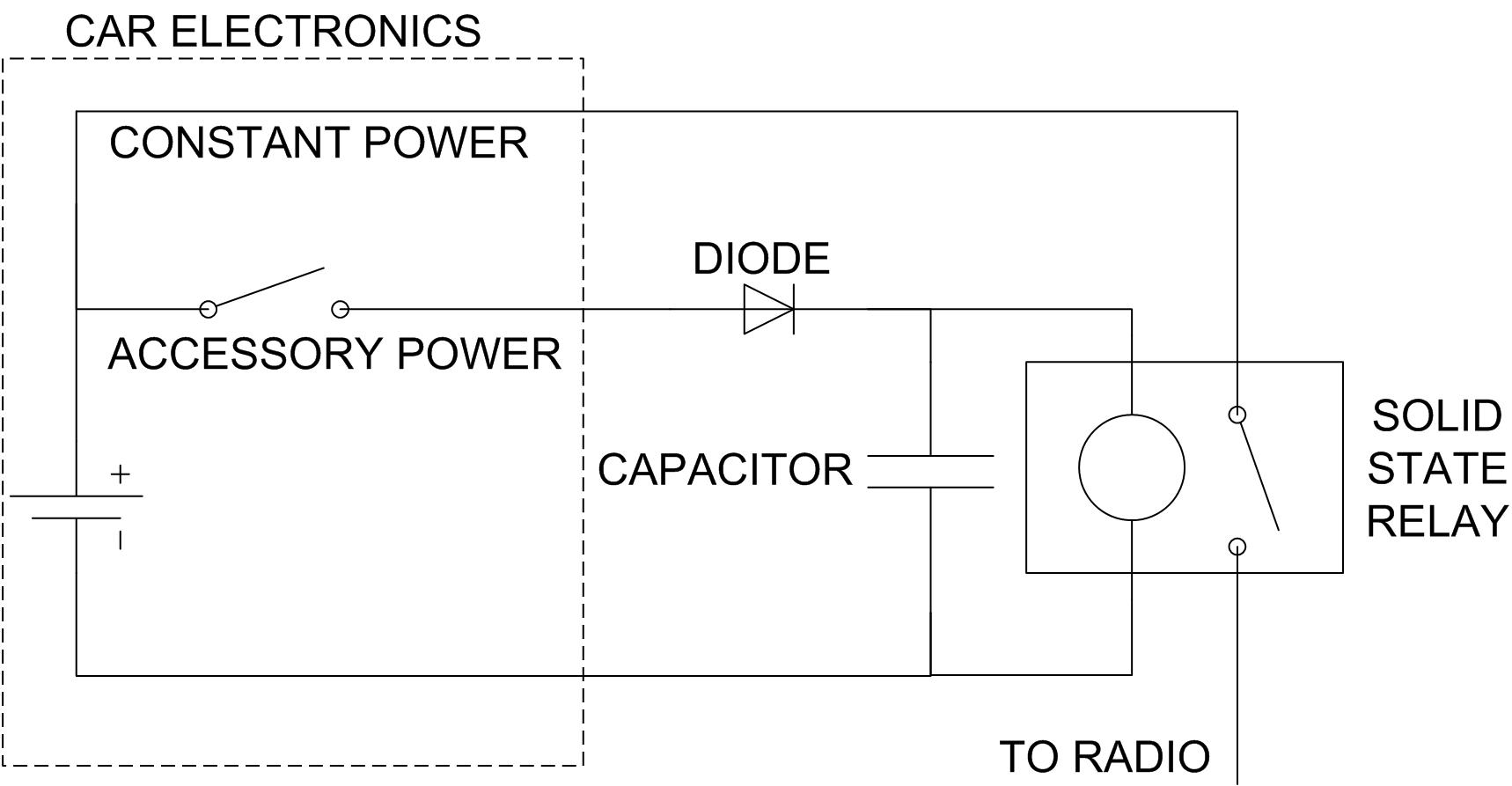
The car radio has the issue of losing track of the CD playback position when the ignition is turned off. This can be problematic during long journeys, especially when leaving an audiobook playing for passengers while refueling. A simple...
A solar cell radio utilizes a 3V power supply, which can be provided by either a single 3V battery or two 1.2V Ni-Cad batteries connected in series. The battery is non-removable, and the device features a mini jack socket...
The circuit serves an educational purpose, necessitating simplicity. The construction will utilize only components that are already available, including a variety of resistors, capacitors, transistors, and no integrated circuits (ICs). The circuit is designed to demonstrate fundamental electronic principles through...