
resistors About a homemade SLA battery charger

The circuit is designed to demonstrate fundamental electronic principles through a straightforward assembly of passive and active components. The choice of components, such as resistors and capacitors, allows for the exploration of basic concepts like voltage division, filtering, and time constants in RC circuits. Transistors will be employed to illustrate their role in signal amplification and switching functions.
For instance, a basic RC low-pass filter can be constructed using a resistor and capacitor in series, with the output taken across the capacitor. This configuration allows for the examination of how the circuit responds to different frequencies, providing insights into the behavior of reactive components. The cutoff frequency can be calculated using the formula f_c = 1 / (2πRC), where R is the resistance and C is the capacitance.
In addition, a simple transistor amplifier can be created using a common-emitter configuration. This setup will involve connecting a transistor with appropriate biasing resistors to ensure it operates in the active region. The input signal can be fed through a coupling capacitor to block any DC offset, while the output can be taken across the load resistor connected to the collector. This arrangement will allow for the analysis of gain and input/output characteristics.
By limiting the construction to available components, the circuit not only serves its educational purpose but also encourages resourcefulness and creativity in circuit design. Overall, this project aims to provide a practical understanding of basic electronic components and their interactions in simple circuits.The circuit has educational purpose, so being simple is a must. I`m also trying to build it only with components that I already have (a bunch of resistors, capacitors, transistors and none IC). 🔗 External reference
Related Circuits
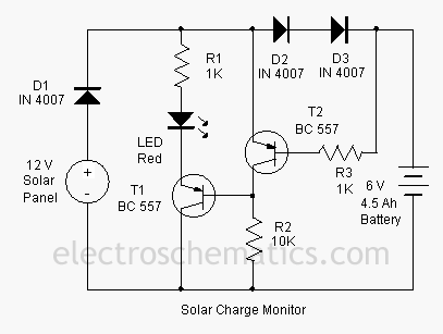
This add-on circuit can be attached to the solar charger to indicate whether the battery is charging. It lights a red LED to signal that the battery is charging. The described add-on circuit serves as a visual indicator for the...
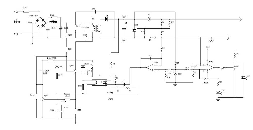
This circuit can automatically and efficiently charge 6V and 12V batteries. A key factor in the successful operation of the circuit is the use of a high-quality transformer [T1] that has excellent insulation and resistance to short circuits. The circuit...
An electrician and businessman named Ton Kuiper has invented a circuit that is claimed to produce longitudinal waves, along with many effects similar to those of Nikola Tesla's technology, while being powered solely by a few nine-volt batteries. A...
This simple battery charger circuit is designed for NiMH/NiCd batteries. It requires no microcontroller or any programming. Linear Technology Corporation. The described battery charger circuit is intended for use with nickel-metal hydride (NiMH) and nickel-cadmium (NiCd) batteries, which are commonly...
This circuit was designed to prevent damage to the 555 timer. It was observed that sharing a high voltage contact with a power connector for the ignition coil caused high voltages to return to the 555 timer, resulting in...
Several schematic drawings of battery charger circuits are provided. These circuits cover 5W to 200W for NiCd, NiMH, Lead-Acid, Li-Ion/Polymer, and LiFePO4 battery packs. The charger circuit files aim to assist users in selecting the appropriate chargers and to...