
Asymmetric Timers

The described astable multivibrator circuit utilizes the 555 timer IC, a versatile component widely used for generating square wave signals. In this configuration, the 555 operates in astable mode, continuously switching between its high and low states without requiring any external triggering.
The timing components consist of two resistors, Ra and Rb, and a capacitor, Ct. The charging phase of the circuit occurs when the capacitor Ct charges through resistor Ra and the 1N4148 diode. The diode's orientation is crucial as it allows current to flow in one direction, ensuring that the capacitor charges effectively. The time constant for the charging phase can be calculated using the formula:
\[ T_{high} = 0.693 \times (Ra + Rb) \times Ct \]
During the discharge phase, the capacitor Ct discharges through resistor Rb into pin 7 (the discharge pin) of the 555 timer. The time constant for the discharging phase can be determined by the following formula:
\[ T_{low} = 0.693 \times Rb \times Ct \]
The output frequency of the astable multivibrator can be derived from the total timing period, which is the sum of the high and low times:
\[ f = \frac{1}{T_{total}} = \frac{1}{T_{high} + T_{low}} \]
This allows for a wide range of frequencies to be generated by adjusting the values of Ra and Rb independently. The astable multivibrator finds applications in various fields, including timer circuits, pulse-width modulation, and frequency generation for clock signals.
For practical implementation, it is essential to select appropriate values for Ra, Rb, and Ct to achieve the desired frequency and duty cycle. Additionally, care must be taken to ensure that the power supply voltage is within the operational range specified for the 555 timer IC, typically between 4.5V and 15V, to ensure reliable operation.A simple astable timer made with the 555, the mark (on) and space (off) values may be set independently. The timing chain consists of resistors Ra, Rb and capacitor Ct. The capacitor, Ct charges via Ra which is in series with the 1N4148 diode. The discharge path is via Rb into into pin 7 of the IC. Both halves of the timing period can now be set i ndependently. 🔗 External reference
Related Circuits
The objective of this circuit is to power a lamp or other device for a predetermined duration (30 minutes in this instance) and subsequently turn it off. This functionality is particularly beneficial for reading in bed at night, as...
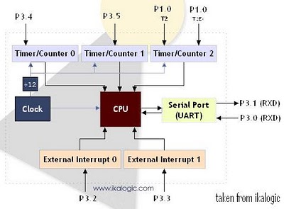
The diagram below illustrates a simplified representation of the main peripherals present in the 89S52 microcontroller, which is part of the 8052/8051 family. The 89S52 includes three Timers/Counters. The term "Timer/Counter" is applicable because this unit can function either...

This is a programmable clock timer circuit that utilizes individual LEDs to indicate hours and minutes. Twelve LEDs are arranged in a circle to represent the 12 hours of a clock face, while an additional 12 LEDs are positioned...
A simple astable timer is constructed using a 555 timer IC. The mark (on) and space (off) durations can be set independently. The timing circuit comprises resistors Ra, Rb, and capacitor Ct. The capacitor Ct charges through resistor Ra,...
This circuit is simple to build and straightforward, but it requires the use of the CMOS type 555 timer designated as the 7555, as a standard 555 timer will not function properly due to the resistor values. A low...
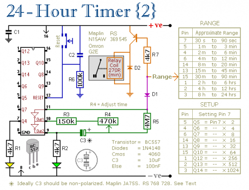
A pair of multi-range timers that provide timing periods of up to 24 hours and beyond. Both timers are fundamentally similar, with the primary distinction being that Version 1 energizes the relay when the time expires, while Version 2...