
Asynchronous power wiring diagram

The three-phase squirrel cage induction motor operates by converting electrical energy into mechanical energy through electromagnetic induction. The prime mover, such as a diesel engine, provides the necessary rotational force to the rotor of the motor. The stator windings generate a rotating magnetic field that induces current in the rotor, facilitating the motor's operation.
In asynchronous power generation mode, the motor operates above its synchronous speed, effectively functioning as a generator. The output of three-phase alternating current is achieved by connecting the stator windings to a load and utilizing capacitors to manage the excitation and voltage levels. The main capacitor (C0) plays a critical role by ensuring that the generator produces the rated voltage under no-load conditions, while the additional capacitors (LCf, 20) are essential for maintaining voltage stability when the motor is under full load.
The selection of capacitors is crucial for the system's performance. Metallized film capacitors or self-healing shunt capacitors are preferred due to their reliability and ability to withstand high voltage levels. The specified minimum rated voltage of 400V ensures that the capacitors can handle the electrical stress without failure.
To size the main capacitor accurately, the equations provided serve as a guideline, allowing engineers to calculate the required capacitance based on the generator's rated voltage and the no-load current. This ensures optimal performance and efficiency of the asynchronous power generation system, contributing to its effectiveness in various applications, including renewable energy systems and backup power solutions.A three-phase squirrel cage induction motor by a prime mover (such as diesel engines, etc.) drag and asynchronous motor stator windings connected to the outlet end and a number of capacitors as excitation power, will be able to output three-phase alternating current. This is called asynchronous power generation mode. Asynchronous power wiring shown in Figure 7-1. Self-excited capacitor is divided into two parts: - Part of the generator to produce the rated voltage at no load, called the main capacitor (c0); the other part of the generator and the load to full load rated voltage kept constant, called the additional capacitance or adjustment capacitors (lCf, 20). Capacitors can be used metallized film capacitors or self-healing shunt capacitors, such as BCMJ, BFF series, the rated voltage is not less than 400V.
The capacitance of the main capacitor can be estimated by the following equation: When used for a rated voltage of 380V generator Cc a 14.5510 (p, F) when used for a rated voltage of 220V generator Co 2510 (and F) where, Io for the restructuring of the asynchronous motor no-load current, a.
Related Circuits
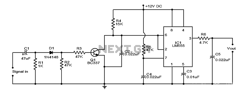
This document provides an overview of a simple circuit diagram for frequency (F and V) voltage conversion. It describes a digital frequency meter circuit primarily based on the LM555 timer IC, which is commonly used in various applications, including...
The WPG DM8168 DaVinci high-definition video System on Chip (SoC) offers multiple DVR/NVR surveillance solutions, utilizing the MT9M033 image sensor as a key component in safety monitoring systems. This solution is complemented by Conexant's line of multi-channel video surveillance...
The circuit utilizes a Zener diode D1 to limit surge voltage and incorporates a four-diode rectifier bridge to prevent reverse voltage. The Zener diode D1 is rated at 36V, with optional choices being 1N4753A or 6KE39A. When the loop...
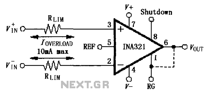
The input current protection circuit for the INA321/322 is illustrated. The INA321/322 features input terminal electrostatic discharge (ESD) protection diodes that become conductive when the input voltage exceeds the supply voltage by 500mV. The protection diodes will conduct, and...
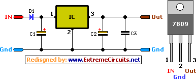
A simple 9 Volt, 2 amp power supply utilizing a single integrated circuit (IC) regulator. This circuit is straightforward, as the regulator handles the majority of the work. The component used is the 7809 voltage regulator. The circuit consists primarily...
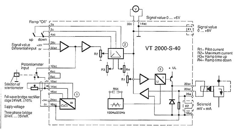
The function is to adjust the time constant associated with a capacitor, thereby influencing the ramp time. The components involved include a transistor, capacitor, and resistor. The circuit described is designed to modify the time constant in an RC (resistor-capacitor)...