
AT89C2051 Digital Thermometer and Clock

The ATMEL 89C4051 microcontroller serves as the central processing unit for the system, equipped with sufficient memory to handle the operations of the A/D converter and LCD display. The HARRIS CA3162 A/D converter is specifically designed for precision voltage measurements, employing a dual-slope integration technique to enhance accuracy and minimize noise. The output format of the converter, being a multiplexed four-bit BCD, allows for seamless communication with the microcontroller, which processes the digitized signals.
The temperature sensing component, the LM35D sensor, is chosen for its linear output, providing a straightforward conversion from temperature to voltage. The low-pass filter composed of a 100k resistor and a 0.02µF capacitor is critical for eliminating high-frequency noise from the temperature signal, ensuring that the readings are stable and accurate before being processed by the A/D converter.
The LCD interface is designed for efficient communication with the microcontroller, utilizing a 4-bit data mode to minimize the number of pins required for operation. The control signals for the LCD are managed through designated pins on the microcontroller, allowing for easy integration and control of the display.
Powering the entire system is accomplished through a 78L05 voltage regulator, which stabilizes the +5V output necessary for the microcontroller and associated components, ensuring reliable operation even when powered by an external +9V adapter. This design encapsulates a robust and efficient electronic measurement system suitable for various applications that require precise temperature readings and digital display output.The MCU is ATMEL 89C4051 CMOS Microcontroller having 4kB code memory, 128 bytes On-chip RAM and 8-bit Port1 and Port3. The A/D chip is HARRIS CA3162, 3-digit DVM. The A/D converter employs dual-slope integrator providing 10Hz sampling rate. Digital output sent to MCU is multiplex four bit BCD started from MSD, LSD and NSD respectively. The MSD signal was tied to P3. 7 indicating first digit ready to be read. Integrating capacitor is a 330nF Polyester type. The 10k POT connected to pin13 is a gain adjustment and 50k POT to pin 8 and 9 is for zero adjustment. The input of the converter is true differential pin 11 for HI and pin 10 LO signal. Temperature was measured by a precision solid-state sensor from National Semiconductor, LM35D. The output signal is 10mV/ °C. Since the A/D converter is capable of providing 0-1000mV reading with 1mV resolution, thus the converter can resolve 0.
1 °C (not absolute accuracy). A 100k and 0. 02uF forms a first order low-pass filter used to be front-end hardware filtering. The 16x1 line LCD is connected in 4-bit interfacing to P1. 4-P1. 7 with control signal RS and E to P3. 4 and P3. 5 respectively. The +5V power supply uses a 78L05 TO92 case with external +9V adapter. 🔗 External reference
Related Circuits
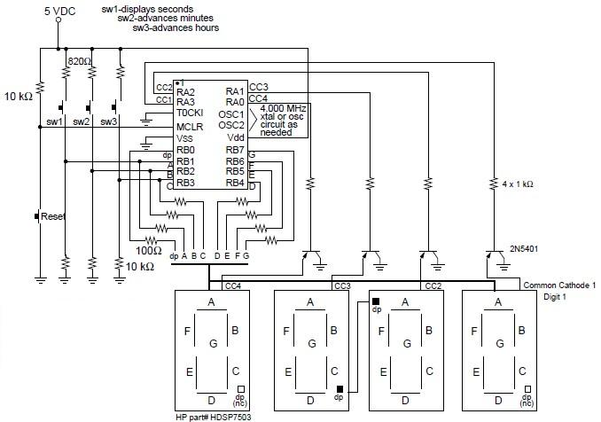
A digital clock project utilizing the PIC16C54 microcontroller can be constructed using the provided circuit diagram. This electronic project features a time-of-day clock that includes four seven-segment LED displays and three input switches. Additionally, there is a reset switch...
The ICL7107 is a 3 1/2 digit LED analog-to-digital converter (A/D converter). It features an internal voltage reference, high-isolation analog switches, sequential control logic, and display drivers. The ICL7107 is designed to convert analog signals into digital representations with a...
This circuit employs a digital voltmeter, consisting of IC1 and IC3, to indicate fuel quantity as a percentage of a full tank. It is designed to accommodate two types of fuel sensors: one with low resistance indicating a full...
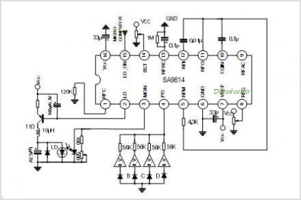
The SA9618A is designed for ALPC and signal conversion between a CD optical pickup and a decoding chip. This integrated circuit (IC) features an interconnection for a general CD optical pickup photodiode bias voltage VREF generation circuit, an RF...
This circuit is designed for precise centigrade temperature measurement. It includes a transmitter section that converts the sensor's output voltage, which is proportional to the measured temperature, into frequency. The output frequency bursts are transmitted through the mains supply...
This circuit allows for amplifier volume control without the need for a potentiometer, utilizing an IC DS1669. The operating voltage for this type of IC ranges from 4.5 volts to 8 volts; however, in this circuit, it is used...