
Digital clock on PIC16C54

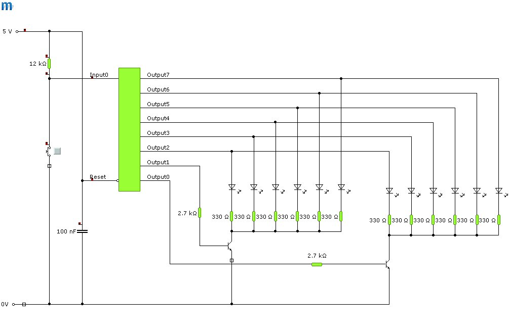
The digital clock circuit operates on the principles of timekeeping and display management using the PIC16C54 microcontroller. The microcontroller serves as the central processing unit, responsible for counting time and controlling the visual output on the LED displays. The four seven-segment displays are arranged to show hours and minutes, with each segment of the display driven by the microcontroller through transistor switches. This configuration prevents the microcontroller from having to source high currents directly, thereby protecting it from potential damage and ensuring reliable operation.
Input switches are incorporated into the design to allow user interaction for setting the time and adjusting the clock. Typically, one switch is designated for incrementing the hours, another for minutes, and the third for toggling between time formats or modes. The additional reset switch, while not standard in final designs, can be useful during development or troubleshooting phases to quickly reset the clock to its initial state.
The choice of common cathode displays is critical, as they provide a straightforward method for controlling the segments. Each segment is connected to the collector of a transistor, which is turned on by a low signal from the microcontroller, allowing current to flow from the common cathode to the segment. The use of 100-ohm resistors in series with the segments is essential for limiting the current to safe levels, ensuring the longevity of the LEDs while maintaining sufficient brightness for visibility. Depending on the specifications of the chosen display, adjustments to the resistor values may be required to achieve optimal performance.
Overall, this digital clock project represents a practical application of microcontroller technology in timekeeping, combining basic electronic components with programming to create a functional and user-friendly device.Digital clock project based on the PIC16C54 microcontroller can be designed using the following circuit diagram. This digital clock electronic project based on the PIC16C54 is a simple time-of-day clock incorporating four seven-segment LED displays and three input switches.
There is also an additional reset switch that would not normally be incor porated into the final design. The displays used were common cathode and turned on with transistors to avoid trying to sink too much current into the PIC16C5X. 100 W resistors were used in series with the segments to obtain the desired brightness. Different values may be required if different displays are used. 🔗 External reference
Related Circuits
A series of digital clocks with LED outputs were developed for the Electronics in Schools Strategy (EiSS) and utilized in various courses organized by SETPOINT (now STEMPOINT) Devon & Cornwall for secondary school educators in the southwest. The initial...
The stock ATS-3A transceiver has been modified to transmit BPSK31 signals, specifically "cq ok1iak." The firmware was altered to enable serial line control through the DASH paddle pin while in straight key mode, which disables the paddle in remote...
Analog-to-digital converters (ADCs), printed-circuit board (PCB), microcontroller or digital signal processor (DSP), total-harmonic-distortion (THD), signal-to-noise ratio (SNR). Analog-to-digital converters (ADCs) are essential components in modern electronic systems, enabling the conversion of analog signals into digital form for processing by microcontrollers...

An FM and AM transmitter integrated into a compact device utilizing the CD4001 integrated circuit. It broadcasts at 20 MHz for AM and 100 MHz for FM. The described transmitter combines both Frequency Modulation (FM) and Amplitude Modulation (AM) capabilities...
This circuit is a small digital roulette. It consists of an oscillator IC1, a counter IC2, and transistors Q1-7 that drive the common cathode display DSP1. The power supply typically comes from a 9V battery, but it can also...
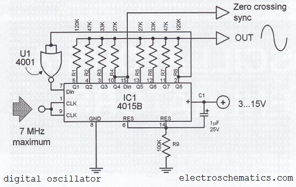
The digital sine wave generator (oscillator) circuit requires only a few components to produce signals with high amplitude constants and a wide range of variable frequencies. This circuit generates a sine wave signal, and by altering the values of...