
Digital Remote Thermometer

The circuit architecture operates on the principle of converting temperature readings into a frequency signal that can be transmitted and processed. The temperature sensor (IC1) is critical for accurate readings, providing a linear voltage output directly related to temperature changes. The voltage-to-frequency converter (IC2) enables the conversion of this output into a frequency signal suitable for transmission over the mains supply, ensuring that the measurement can be counted and displayed remotely.
The use of Q1 as a driver for Q2 allows for effective amplification of the frequency signal, ensuring that the signal remains robust even after transmission. The filtering and limiting components (C5, D1, D2) are essential for maintaining signal integrity, preventing distortion that could lead to inaccurate readings.
The counting and display mechanism is managed by IC5, which interprets the frequency pulses and translates them into a human-readable format on the 7-segment displays. The multiplexing approach, facilitated by Q2, Q3, and Q4, allows for efficient display management, ensuring that the readings are updated in real-time without flickering.
Overall, this circuit design exemplifies a sophisticated method for temperature measurement and display, utilizing frequency modulation to transmit data effectively while maintaining accuracy and reliability across its components.This circuit is intended for precision centigrade temperature measurement, with a transmitter section converting to frequency the sensor`s output voltage proportional to the measured temperature. The output frequency bursts are conveyed into the mains supply cables. The receiver section counts the bursts coming from mains supply and shows the coun ting on three 7-segment LED displays. The least significant digit displays tenths of degree and then a 00. 0 to 99. 9 G‚ °C range is obtained. IC1 is a precision centigrade temperature sensor with a linear output of 10mV/G‚ °C driving IC2, a voltage-frequency converter. At its output pin (3), an input of 10mV is converted to 100Hz frequency pulses. Thus, for example, a temperature of 20G‚ °C is converted by IC1 to 200mV and then by IC2 to 2KHz. Q1 is the driver of the power output transistor Q2, coupled to the mains supply by L1 and C7, C8. The frequency pulses coming from mains supply and safely insulated by C1, C2 & L1 are amplified by Q1; diodes D1, D2 limiting peaks at its input.
Pulses are filtered by C5, squared by IC1B, divided by 10 in IC2B and sent for the final count at the clock input of IC5. IC4 is the time-base generator: it provides reset pulses for IC1B and IC5 and enables latches and gate-time of IC5 at 1Hz frequency.
It is driven by a 5Hz square wave obtained from 50Hz mains frequency picked-up from T1 secondary, squared by IC1C and divided by 10 in IC2A. IC5 drives the displays` cathodes via Q2, Q3 & Q4 at a multiplexing rate frequency fixed by C7. It drives also the 3 displays` paralleled anodes via the BCD-to-7 segment decoder IC6. 🔗 External reference
Related Circuits

A simple device that enables a quick check of common infrared remote controls can be beneficial for electronics enthusiasts often tasked with repairing or testing these widely used devices. A dependable circuit has been designed using a few components:...
The following circuit illustrates a Radio Remote Control Circuit Diagram. This circuit is based on the UM91214B IC. Features include the use of DTMF (dual-tone multi-frequency) technology. The Radio Remote Control Circuit utilizes the UM91214B integrated circuit, which is specifically...

The goal of Advanced Digital Electronics courses is to connect basic logic gates (combinational circuits) with technical subjects related to binary counter topologies (both Asynchronous and Synchronous), shift registers, memory, and Digital Signal Processors (DSP), which are categorized as...
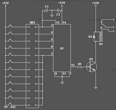
The Digital Combination Lock Circuit is a schematic for a simple electronic combination lock utilizing the LS7220 integrated circuit (IC). This password-protected digital lock can activate a relay to control any device by entering a preset combination of four...
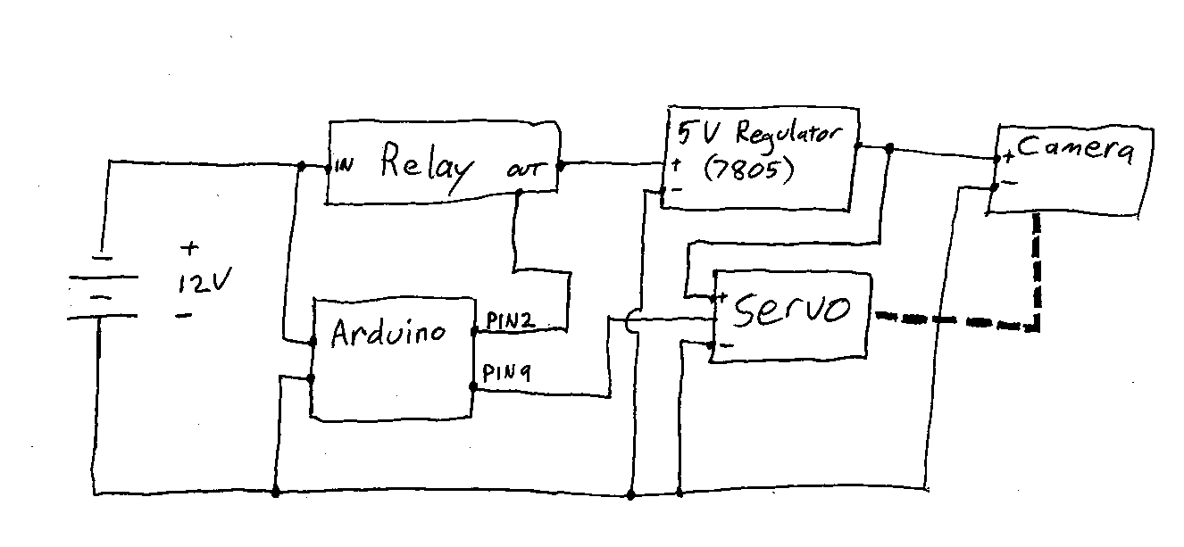
Information and resources on remotely using a DSLR camera, primarily utilizing Arduino-based solutions. The use of Arduino-based systems for remotely controlling DSLR cameras has gained popularity among photography enthusiasts and professionals seeking to enhance their shooting capabilities. These systems typically...
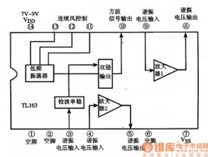
The following circuit illustrates the TL163 integrated circuit (IC) used in an ultrasonic remote control circuit diagram. Features include a detector, high-gain amplifier, and low-frequency response. The TL163 IC is designed to facilitate ultrasonic signal processing, making it suitable for...