
AT89xx051 PROGRAMMER

The circuit requires a 15V DC power supply, which serves as the input voltage for the voltage regulator, specifically the 7812 model. The 7812 voltage regulator is designed to output a stable 12V DC from a higher voltage input. To ensure proper operation and stability of the voltage regulator, an electrolytic capacitor is recommended across the input terminals of the regulator. This capacitor helps filter out any voltage spikes or fluctuations from the power supply, providing a smoother input voltage to the regulator.
When a capacitor is connected to the output pin of the 7812 with respect to ground, it is essential to include a bypass diode. This diode should be connected in reverse orientation between the input and output pins of the regulator. The purpose of this diode is to prevent any potential reverse voltage that may occur, which could damage the regulator. In normal operation, the diode remains reverse-biased, effectively isolating the input from the output. However, in the event of a fault condition or sudden voltage drop, the diode will conduct, protecting the regulator from reverse voltage and ensuring reliable circuit performance.
In summary, this circuit configuration emphasizes the importance of using an electrolytic capacitor for input stability and a bypass diode for protection against reverse voltage, thus ensuring the longevity and reliability of the 7812 voltage regulator in various applications.It requires a 15VDC adapter. An electrolyte capacitor is needed across the regulator input. If the capacitor is added in 7812`s OUT pin w. r. t. ground, then a bypass diode should be added in reverse to IN and OUT of the regulator, just to save it from reverse voltage. 🔗 External reference
Related Circuits
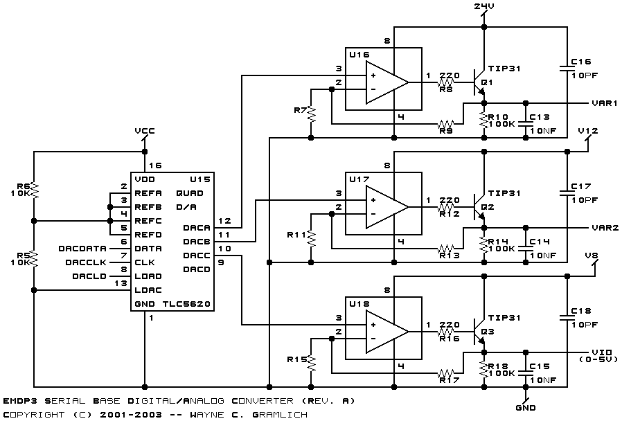
The power supply utilizes an Underwriters Laboratory® approved "wall wart" to deliver 24VDC of power, ensuring that the base board does not have any 110V AC or similar voltages present. Power can be supplied through either N1 (on-board) or...
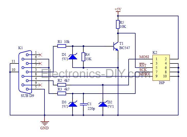
This is a simple AVR programmer designed for Atmel microcontrollers from the AVR family that support serial programming. The programmer connects to a PC via the RS232 serial interface and is compatible with PonyProg or Avrdude software. It is...
This is my own version of the classic PIC 16C84/16F84 programmer. The design is originally by David Tait. I’ve made a few changes, redrawn the schematic and done a board layout. All the files you will need are linked...
This is a beta release schematic. Use at your own risk. The idea is to add this circuitry to a board that already has RAM at address 2000 and an 82C55 I/O chip to provide ports A, B, and...
The Flash MC Programmer II is a rapid parallel port programmer designed for various 40-pin 8051 microcontrollers. The Flash MC Programmer II employs a parallel port interface to facilitate high-speed programming of 40-pin 8051 microcontrollers. This device is particularly advantageous...
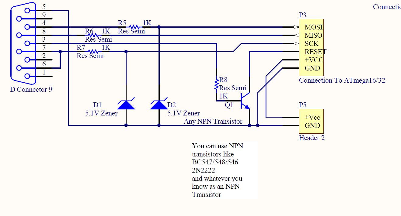
ISP programmer with circuit diagram for AVR Atmega32 microcontroller. This ISP burner circuit is an adaptation of the Pony programmer and uses PonyProg software. The ISP (In-System Programming) programmer designed for the AVR Atmega32 microcontroller facilitates the programming of the...