
ISP Programmer/Burner with circuit diagram for AVR Atmega Micro Controller

The ISP (In-System Programming) programmer designed for the AVR Atmega32 microcontroller facilitates the programming of the microcontroller directly on the target circuit. This approach allows for the microcontroller to be programmed without the need for removal from its operational environment, which is essential for applications where space and accessibility are limited.
The circuit diagram for the ISP programmer typically includes a microcontroller interface, a connection to a PC, and the necessary components to support communication protocols. Key components of the circuit include resistors, capacitors, and a crystal oscillator, which are essential for stable operation and timing. The Pony programmer adaptation utilizes a serial interface for communication with the PC, allowing the user to upload firmware to the Atmega32.
Connections to the Atmega32 microcontroller are made through specific pins designated for programming. These include the MOSI (Master Out Slave In), MISO (Master In Slave Out), SCK (Serial Clock), RESET, and VCC/GND pins. The circuit must ensure proper voltage levels and signal integrity to avoid programming errors.
The software used, PonyProg, is compatible with various operating systems and provides a user-friendly interface for firmware uploading. It supports various programming modes and offers diagnostic features to ensure successful programming.
In summary, the ISP programmer circuit for the Atmega32 microcontroller is a vital tool for developers, enabling efficient firmware updates and programming directly in the application environment. The adaptation of the Pony programmer enhances its functionality and ease of use, making it an effective solution for embedded systems development.ISP programmer with circuit diagram for AVR Atmega32 micro controller.This ISP burner circuit is an adaptation of Pony programmer and uses ponyprog software.. 🔗 External reference
Related Circuits

A method for measuring static electricity for a science project was sought. An old copy of "Getting Started in Electronics" by Forrest M. Mims III was referenced for guidance. To create a static electricity measurement circuit, a simple design can...
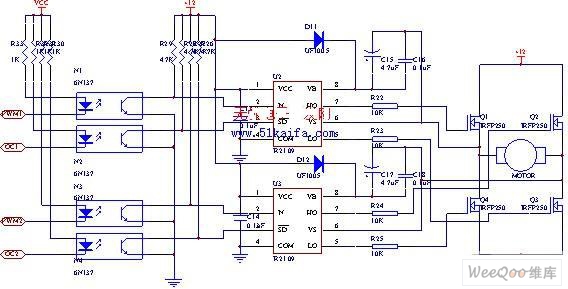
The drive circuit for the electromotor comprises a FET bridge circuit, a FET base drive circuit, a current sensor for the motor drive circuit, and a relay. The FET bridge circuit primarily consists of four high-power MOSFETs, which must...
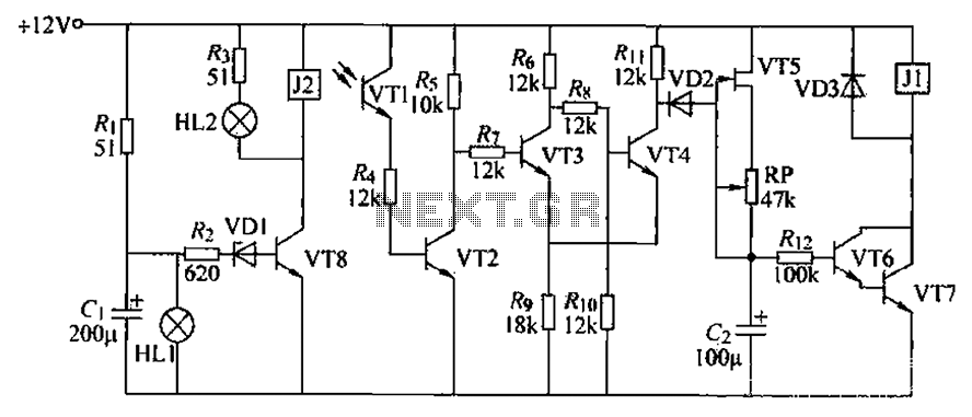
A blocking material monitoring circuit is presented. When the optical path is obstructed by the material, the phototransistor VT1 turns off, which subsequently turns off transistors VT2, VT3, and VT4. This arrangement is coupled to a flip-flop configuration. When...

This is a design for a low noise microphone preamplifier, which is ideally suited to low impedance (600 Ohm nominal) microphones. One limitation is that it is not balanced, which is not a problem in a home recording environment,...
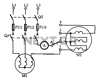
Drying the motor winding circuit current imbalance. Below is a circuit diagram of the motor winding current imbalance drying. The circuit for drying motor winding current imbalance is designed to address the issue of uneven current distribution across the windings...
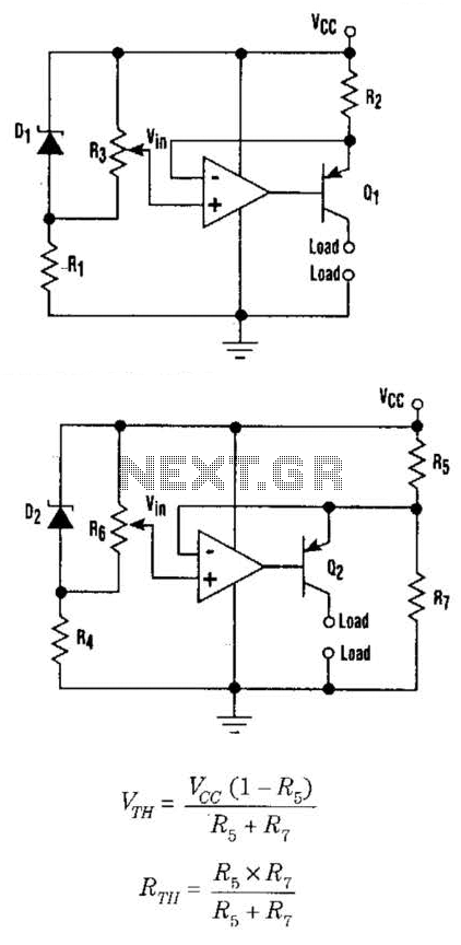
This setup can function as a cost-effective current source with an output accuracy of 1%. However, the voltage offset can activate the current source even when Vqq equals Vin. Modifying the configuration of Figure 1 can resolve the issue...