
2 -Y-connected two-speed motor contactor control circuit

The circuit design utilizes two distinct operational buttons, SB2 and SBi, to control the speed of a connected device or system. SB2 is configured to engage a low-speed mode, likely by controlling the voltage or current supplied to the load, thereby enabling smoother operation at reduced speeds. This mode may be beneficial for applications requiring precision or reduced wear on mechanical components.
Conversely, SBi activates a high-speed mode, allowing for increased performance and faster operation. This button may bypass certain resistive elements or activate additional power stages within the circuit to achieve the desired high-speed functionality. The transition between these two operational states is crucial for applications that demand flexibility in speed control, such as in motors, fans, or other electromechanical systems.
To ensure reliable operation, the circuit may incorporate additional components such as resistors, capacitors, or diodes to manage the electrical characteristics during the switching process. Proper design considerations must be taken into account to prevent issues such as voltage spikes or excessive current draw, which could potentially damage the system.
Overall, the circuit's functionality is determined by the effective implementation of the low-speed and high-speed operation buttons, allowing users to tailor the performance of the connected device to meet specific operational requirements. Circuit shown in Figure 3-104. in graph. SB2 is running at low speed button, SBi as the high-speed operation button.
Related Circuits
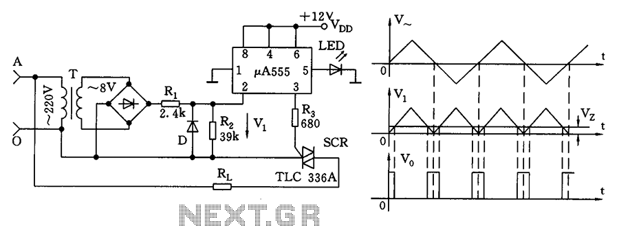
The zero volt switching circuit generates a trigger pulse at the zero crossing of the AC voltage. To facilitate this, the zero crossing of the 555 limit comparator is connected to a single form, with the comparison voltage set...
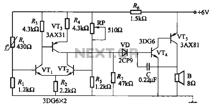
A negative temperature coefficient thermistor is utilized as the temperature sensing element (Rt). The circuit includes a resistor (Ri), a resistor (Rs), a potentiometer (RP), and the thermistor (R) to form a temperature bridge. A differential amplifier is created...
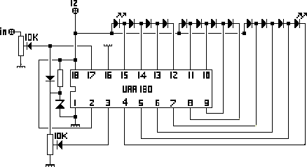
The NL3ASD schematic pages provide the schematics for a LED VU meter utilizing the UAA180 integrated circuit. The NL3ASD schematic pages feature a comprehensive design for a LED VU meter that employs the UAA180 IC, known for its audio signal...
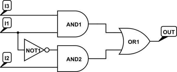
There are integrated circuits that contain AND, OR, and NOT gates. The inquiry revolves around the existence of a single chip that encompasses all the required logic gates. If such a chip does not exist, specific alternatives should be...
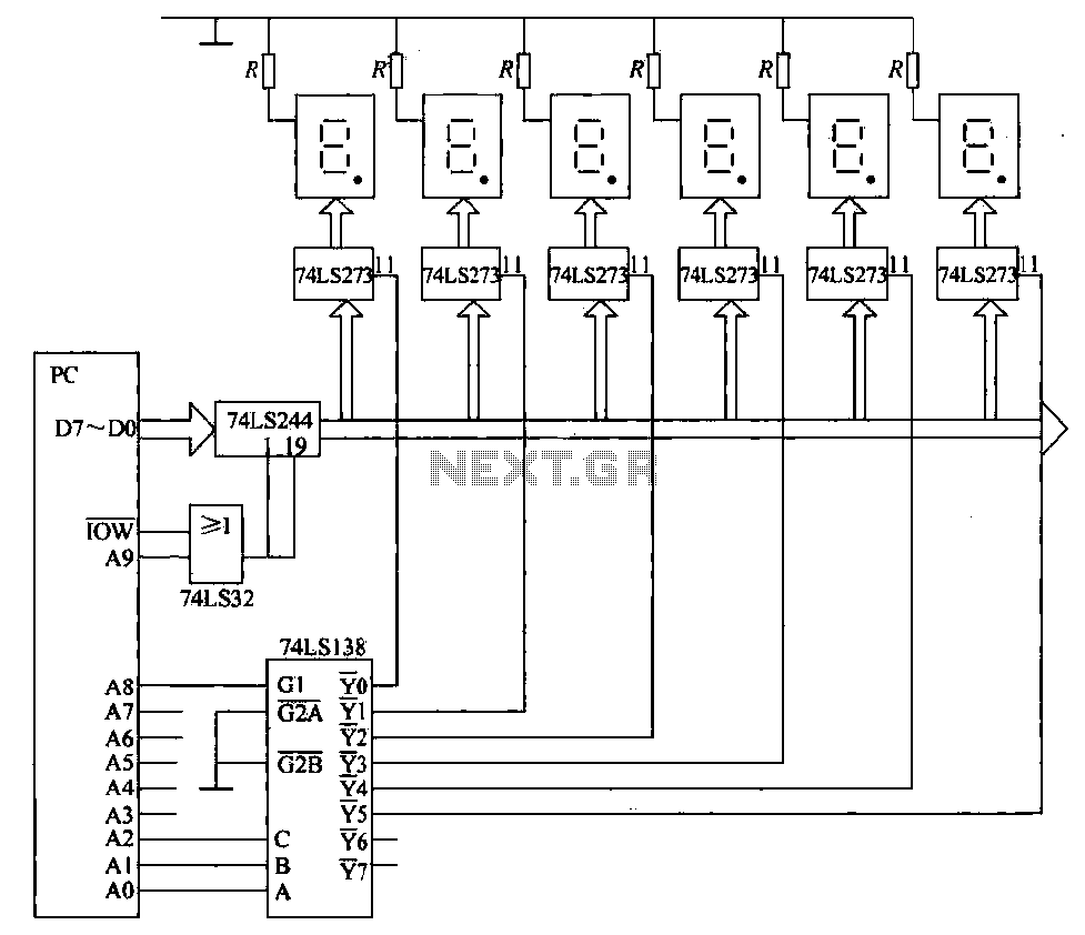
The static display circuit is illustrated in Figure 6. The 74LS244 acts as bus drivers, and six figures represent a public bus, each equipped with an LED display latch (like the 74LS273) connected to the code for latching the...
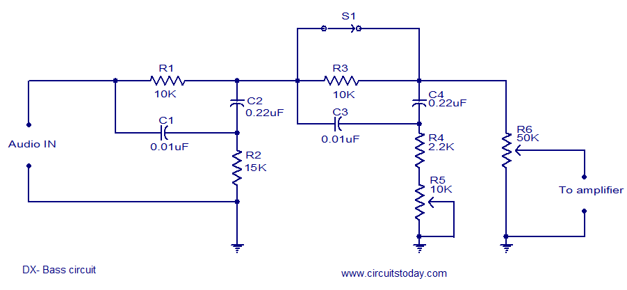
The circuit diagram of a passive DX bass circuit is presented, which is compatible with nearly all audio amplifiers. This design was created by Mr. Emmanuel Chipula from Malawi and submitted for publication. Laboratory tests confirmed satisfactory performance. Credit...