
Atmel At90S2313 Countermeasures

The implementation involves constructing an 8-bit data bus using the lower four bits of PORTD and the upper four bits of PORTB on the AT90S2313. This configuration is necessary to utilize the OC1 output on PB3 for gating the counter stage. The display consists of three-digit, common-cathode, seven-segment displays that are multiplexed by sending segment data from the data bus and selecting the active digit using an HC138 data selector controlled by three I/O lines from the AT90S2313. Two HC590 counters are employed to count input pulses, providing the count to the AT90S2313 via the data bus. Each counter can be read independently using the OE_L and OE_H lines, while the counters are reset using the CLR signal. The gating of the counters is managed by the OC1 signal from the AT90S2313, allowing for varying gate durations to facilitate autoranging and accommodate a wide frequency range.
The software for the counter is developed in C, prioritizing simplicity over speed, as high-speed operations are handled externally by the counters and Timer1 within the AT90S2313. The frequency measurement process is straightforward: the counters are enabled for 1 ms, and if the count exceeds 4096 (indicating frequencies above 4.096 MHz), the result is displayed, followed by a new count. If the count is below 4096, a longer gate time of 10 ms is employed for improved resolution, and the process is repeated. If the count remains below 4096, the system switches to 100 ms or down to 1 second to capture lower frequencies accurately.
This circuit design exemplifies a practical approach to frequency counting, leveraging both hardware and software components to achieve reliable performance across a range of input frequencies. The careful consideration of power consumption, display multiplexing, and gating techniques ensures that the device operates efficiently while providing accurate frequency measurements.This is another project which fullfills a need. I once built a frequency counter using plain TTL chips. That was long before the CMOS HC versions, even before LS was available. It uses only 4 chips - 3 HC TTL`s and an Atmel At90S2313 microcontroller. It has a 5 digit LED display plus one used as a band indicator. Even with the LED display, the cur rent consumption is less than 50 mA. It counts up to at least 52 MHz. I couldn`t find any signal source in the lab that could supply more than 52 MHz, so it may go a bit higher, but the fClock(typ) for the HC590 is about 35-40 MHz, so you shouldn`t really count (no pun intended) on more. I got the idea from an article I saw on the net. I think it was a Circuit Cellar article. I had a look at the code, and it sounded like a quick and simple counter solution. I don`t know what chips it used, as I never saw the schematic, but here`s my implementation : A 8-bit "databus" is constructed from the lower 4 bits of PORTD and the upper 4 bits of PORTB on the 2313.
This peculiar arrangement is necessary, as we need the OC1 output on PB3 for gating the counter stage. The displays are 3-digit 7-segment common-cathode displays. They are multiplexed by supplying the segment data from the databus, and selecting the current digit with a `HC138 dataselector, which is controlled by 3 I/O lines from the 2313.
The two `HC590 counters are counting the input pulses and supplies the count to the 2313 on the databus. Each counter can be read separately using the OE_L and OE_H lines. The counters are cleared using the CLR signal. The counters are gated using the OC1 (Output Compare 1) signal from the 2313. By varying the duration of the gate time, the counter can be made autoranging, and handle a large frequency span.
The software for the counter is written in C-code, as speed is not an issue. All high-speed handling is done by the external counters and the Timer1 in the 2313. The method of measuing a frequency is simple. First, the counters are enabled for 1 mS. If the count is larger than 4096 (4. 096 MHz), the count is shown on the display, and a new count is made. If less that 4096, we can get better resolution with a larger gate time, so we try 10 mS. Again, if the count is larger than 4096 (409. 6 KHz), the count is shown, otherwise we try 100mS, or down to 1 S. 🔗 External reference
Related Circuits
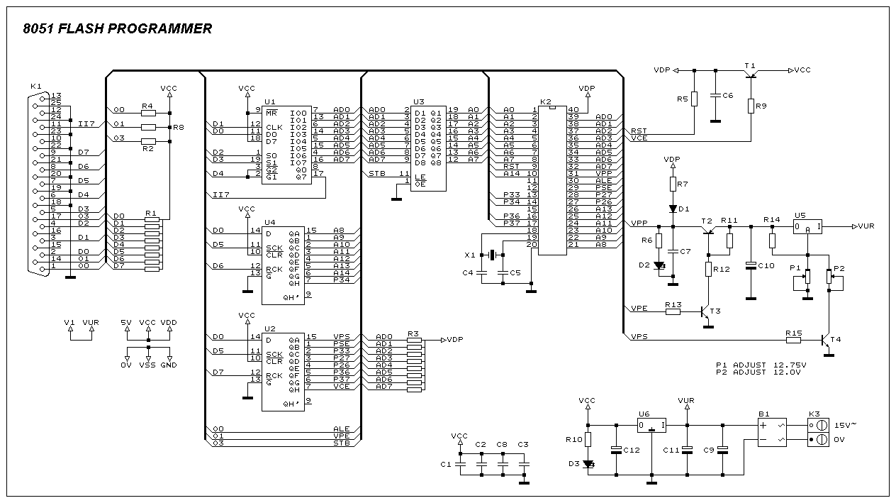
This programmer was designed to be flexible, economical, and easy to build. The programmer hardware utilizes standard TTL series parts, and no special components are used. The programmer is interfaced with the PC parallel port, and there are no...
Diode D1 and resistor R1 provide VDD isolation during the programming of 24-pin devices. Jumper J3 must be shorted for 24-pin devices and left open for programming 28-pin devices. The following EEPROMs are pin compatible with their EPROM versions. In...
The Atmel Flash devices are ideal for developing, since they can be reprogrammed easy and fast. If you need more code space for your application, particularly for developing 89Cxx projects with C language. Atmel offers a broad range of...
This ISP programmer can be utilized for both in-system programming and as a standalone SPI programmer for Atmel ISP programmable devices. The programming interface is compatible with the STK200 ISP programmer hardware, allowing users of the STK200 to also...
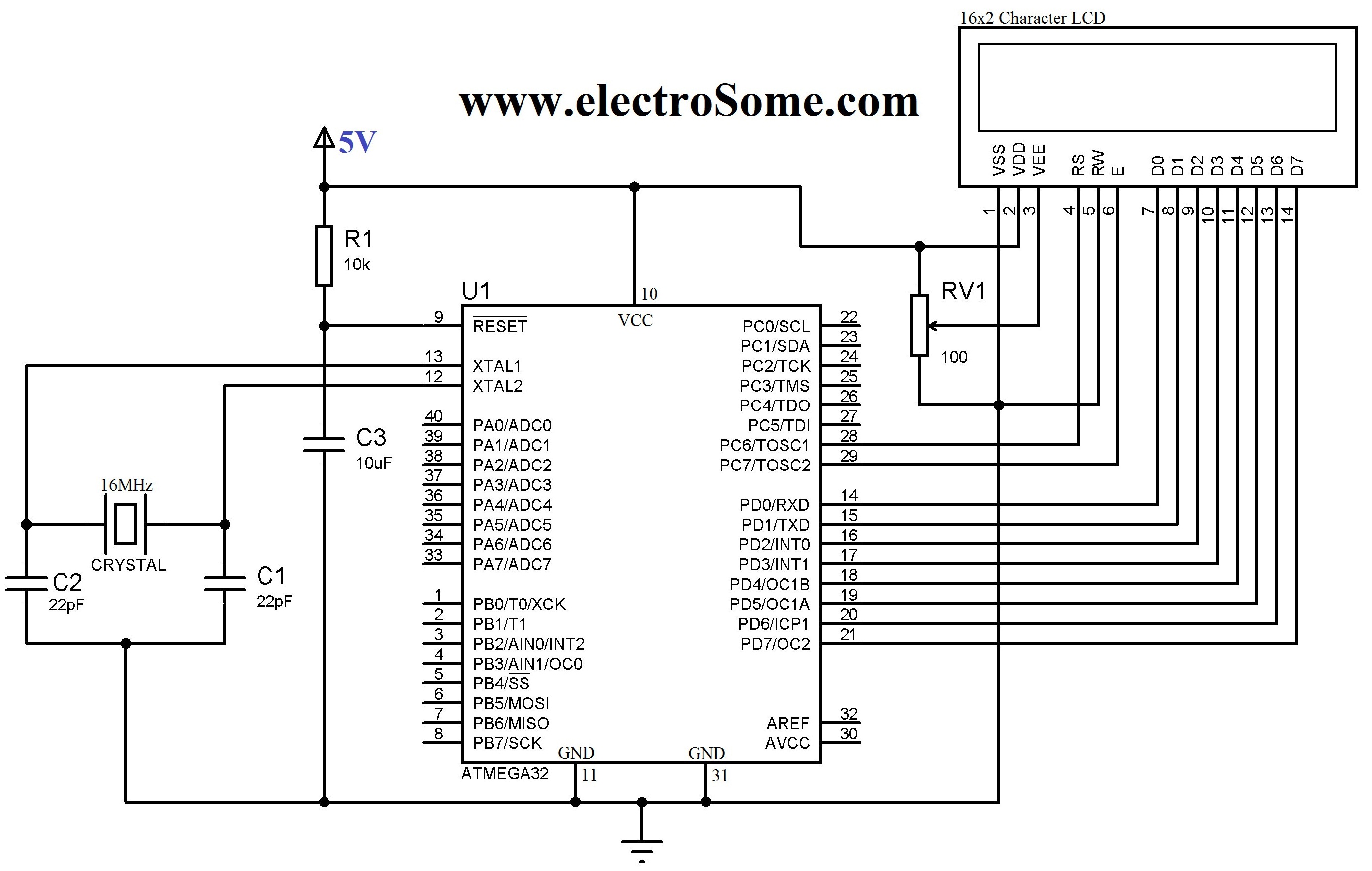
An LCD (Liquid Crystal Display) is a widely used electronic display found in devices such as calculators, laptops, tablets, and mobile phones. The 16G-2 character LCD module is a fundamental component frequently utilized by electronics enthusiasts and integrated into...
Many applications require a large number of keys connected to a computing system. Examples include PC keyboards, cell phone keypads, and calculators. Connecting a single key to a microcontroller unit (MCU) is straightforward; however, connecting 10 or 100 keys...