
interfacing lcd atmega32 microcontroller atmel studio

The library provides functions for cursor control and character writing. The functions `Lcd8_Set_Cursor()` and `Lcd4_Set_Cursor()` set the cursor position on the LCD by specifying the desired row and column. The functions `Lcd8_Write_Char()` and `Lcd4_Write_Char()` write a single character to the LCD, incrementing the cursor position accordingly. The functions `Lcd8_Write_String()` and `Lcd4_Write_String()` are used to display strings on the LCD, advancing the cursor by the length of the string plus one.
The code snippet demonstrates the initialization and usage of the LCD in both 8-bit and 4-bit modes. It sets the data direction registers for ports D and C to output, initializes the LCD, and enters a loop where it displays a scrolling message. The scrolling effect is achieved by shifting the displayed text left and right, with a brief delay between shifts. The program concludes by clearing the display and writing individual characters.
The library is defined with specific macros for pin assignments, including data pins D0 to D7 and control pins RS and EN. The clock speed for the microcontroller is defined as 16 MHz, ensuring proper timing for operations. The header file for the LCD library can be downloaded from the referenced article, allowing users to easily implement the functions in their projects.
This comprehensive approach to interfacing the 16G-2 LCD with the Atmega32 microcontroller provides a robust solution for displaying information in various electronic applications, making it an invaluable resource for hobbyists and engineers alike.LCD (Liquid Crystal Display) is an electronic display which is commonly usednowadaysin applications such as calculators, laptops, tablets, mobile phones etc. 16G—2 character LCD module is a very basic module which is commonly used by electronic hobbyists and is used in many electronic devices and project.
It can display 2 lines of 16 character and each character is displayed using 5G—7 or 5G—10 pixel matrix. Interfacing 16G—2 LCD with Atmega32 Atmel AVR Microcontroller using Atmel Studio is bit complex as there is nobuiltin libraries. To solve this difficulty we developed a LCD library which includes the commonly used features. Just include our header file and enjoy. You can download the header file from the bottom of this article. 16G—2 LCD can be interfaced with a microcontroller in 8 Bit or 4 Bit mode. These differs in how data and commands are send to LCD. In 8 Bit mode character data (as 8 bit ASCII) and LCD command aresentthrough the data lines D0 to D7.
That is 8 bit data is send at a time and data strobe is given through E of the LCD. But 4 Bit mode uses only 4 data lines D4 to D7. In this 8 bit data is dividedintotwo parts and aresentsequentially through the data lines. The idea of 4 bit communication is introduced to save pins of microcontroller. 4 bit communication is bit slower than 8 bit but this speed difference has no significance as LCDs are slow speed devices. Thus 4 bit mode data transfer is most commonly used. #define D0 eS_PORTD0 #define D1 eS_PORTD1 #define D2 eS_PORTD2 #define D3 eS_PORTD3 #define D4 eS_PORTD4 #define D5 eS_PORTD5 #define D6 eS_PORTD6 #define D7 eS_PORTD7 #define RS eS_PORTC6 #define EN eS_PORTC7 Lcd8_Set_Cursor() & Lcd4_Set_Cursor() :These function will set the cursor position on the LCD screen by specifying its row and column.
By using these functions we can change the position of character and stringdisplayedby the following functions. Lcd8_Write_Char() & Lcd4_Write_Char() :These functions will write a single character to the LCD screen and the cursor position will be incremented by one.
Lcd8_Write_String() & Lcd8_Write_String() :These function will write string or text to the LCD screen and the cursor positon will beincrementedby length of the string plus one. #ifndef F_CPU #define F_CPU 16000000UL // 16 MHz clock speed #endif #define D0 eS_PORTD0 #define D1 eS_PORTD1 #define D2 eS_PORTD2 #define D3 eS_PORTD3 #define D4 eS_PORTD4 #define D5 eS_PORTD5 #define D6 eS_PORTD6 #define D7 eS_PORTD7 #define RS eS_PORTC6 #define EN eS_PORTC7 #include
h> #include
h, you can connect your 16G—2 LCD to any of the output pins of the microcontroller. More coding is required for this feature which reduces the code efficiency and increases the size of hex file. You can solve this problem by m 🔗 External reference
Related Circuits
The ATA5423, ATA5425, ATA5428, and ATA5429 are highly integrated UHF ASK/FSK multi-channel half-duplex transceivers characterized by low power consumption. These devices are housed in a compact 7 x 7 mm QFN48 package. The receiving section features a fully integrated...
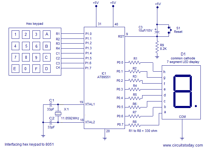
Interfacing a hex keypad to an 8051 microcontroller. The AT89S51 is utilized in this setup. A circuit diagram and assembly language program are included. A testing video is also provided. The interfacing of a hex keypad with the AT89S51 microcontroller...
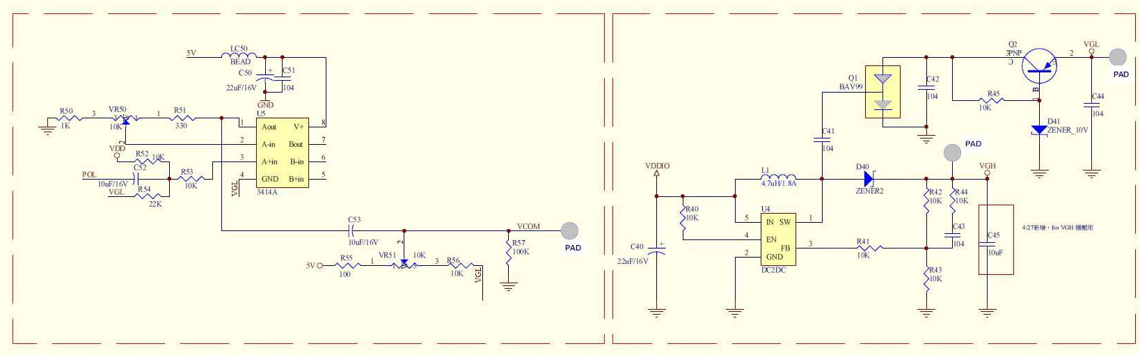
A circuit provided by an LCD manufacturer illustrates the use of the POL signal from the display to derive the VCOM signal. It has been noted that LCD Bias ICs typically generate VCOM from a high bias voltage. The...
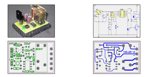
The ability to turn electrical devices ON or OFF using a remote control is a well-established concept, with numerous devices effectively performing this function. To implement a remote control system for switching electrical devices, a typical schematic would include several...
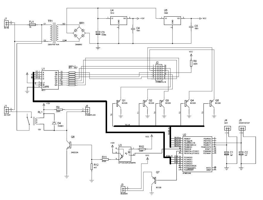
The procedure outlines the construction of a Box, Lamp System, and Countdown System utilizing the AVR Mega8 microcontroller. The system features four blacklight lamps, each rated at 15W, which emit radiation primarily in the UVA spectrum, peaking around 350nm,...
This project measures the clock pulses supplied to the Timer input of the AVR microcontroller. The Bascom code counts the clock pulses over a duration of 1 second and displays the result. The circuit for this project primarily consists of...