
audible logic probe

The logic probe described functions as an effective diagnostic tool for TTL (Transistor-Transistor Logic) circuits, facilitating easier troubleshooting by providing auditory feedback rather than relying solely on visual indicators. The probe's design incorporates a simple yet efficient audio output mechanism that enhances usability during circuit evaluations.
The device operates on a 5-volt power supply, which is standard for TTL logic levels. The ground connection is crucial as it establishes a common reference point for the circuit under test and the probe itself, ensuring accurate voltage readings. The probe's input lead is equipped to connect with various points within the circuit, allowing for comprehensive testing of multiple chips and components.
When the logic probe detects an input voltage greater than 2 volts, it signifies a logical high state. This is conveyed through a high-pitched tone emitted by the built-in speaker, allowing the user to quickly ascertain the status of the circuit without needing to divert attention to LED indicators. In contrast, when the input voltage falls below 0.8 volts, the probe indicates a logical low state, producing a lower tone. This auditory feedback is particularly beneficial in complex circuits where multiple signals may need to be monitored simultaneously, enabling the user to maintain focus on the circuit while still receiving real-time updates on the logic states.
For applications involving CMOS (Complementary Metal-Oxide-Semiconductor) circuits, modifications may be required to accommodate the different voltage levels typically associated with CMOS technology. However, the fundamental principles of operation remain consistent, providing a versatile tool for a variety of digital circuit testing scenarios.When testing circuits with a logic probe, it is sometimes difficult to watch the LEDS on the probe to determine the logic state. With this probe the logic states are audible. This probe is designed for TTL circuits only but could be modified for CMOS. The way it works is as follows. The 5 volt power source will be the circuit under test. Clip the ground input of the probe to the ground of the circuit being tested. The other input lead is used to probe the different chips of the circuit being tested. Any input greater then 2 volts will be high and output a high tone through the speaker. Any input less then. 8 volts will be low and produce a low tone through the speaker. 🔗 External reference
Related Circuits
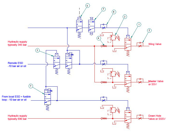
Filter regulators, solenoid valves, quick exhaust valves, flowline pilots - Welcome to Bifold Fluidpower Ltd. Bifold Fluidpower Ltd. specializes in a range of fluid power components that include filter regulators, solenoid valves, quick exhaust valves, and flowline pilots. Each of...
The design of the digital logic probe centers around a pair of complementary bipolar transistors, which, in this application, are used as electronic switches. The digital logic probe is a diagnostic tool utilized for testing and analyzing digital circuits. The...
This circuit is not a novelty, but it proved so useful, simple and cheap that it is worth building. When the positive (Red) probe is connected to a DC positive voltage and the Black probe to the negative, the...
The capacitance between the wire and the probe would form a capacitive voltage divider with the probe's input capacitance, and at frequencies significantly higher than the low frequency roll off created by the probe's input capacitance and the probe's...
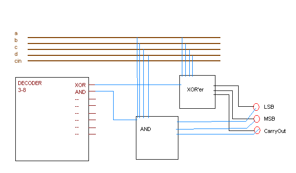
A 2-bit ALU is being created with eight defined functions, which are identified by a 3-bit code. These functions include operations such as AND and XOR, and they operate on two 2-bit binary numbers to produce a 2-bit output....
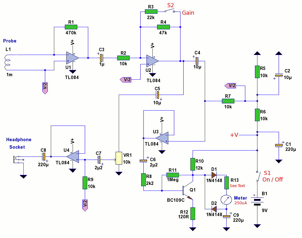
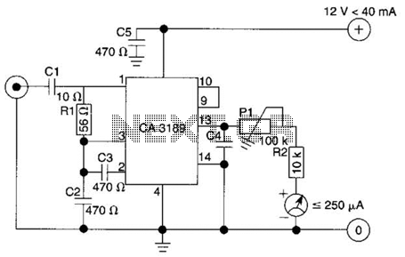
An electromagnetic field probe designed to detect changing electric and magnetic fields. The probe features switchable gain, a frequency response of up to 400 kHz, and independent audio and meter monitoring. This EMF probe utilizes an inductor to locate...