
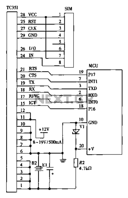
door alarm system schematic

The circuit operates on the principle of capacitive sensing, where the touch on the door handle is detected by a capacitive touch sensor. The sensor is connected to a microcontroller or a dedicated touch sensing IC that interprets the capacitive change caused by the human touch. Upon detection, the microcontroller activates a piezo buzzer and an LED indicator.
The schematic includes a power supply circuit that provides the necessary voltage to the microcontroller and the output devices. Typically, a 5V DC power supply is used, which can be derived from batteries or an AC-DC adapter. The touch sensor is connected to one of the GPIO (General Purpose Input/Output) pins of the microcontroller.
When the door handle is touched, the microcontroller receives a signal from the touch sensor, triggering the output. The piezo buzzer emits a sound, while the LED lights up, providing both auditory and visual indications of the alert. The duration of the alarm can be programmed based on the desired response time.
To ensure the circuit can be reset, a manual switch is included, allowing the user to turn off the alarm after the alert has been acknowledged. Additionally, the circuit may incorporate a delay mechanism to prevent false alarms due to environmental factors, such as wind or rain.
Overall, this circuit provides a practical solution for alerting homeowners to potential intrusions, enhancing security through simple yet effective electronic design.This circuit Schematics a beep and/or illuminates a LED when someone touches the door-handle from outside, alarm will sound until the circuit will be switched-off.. 🔗 External reference
Related Circuits

The water tank overflow liquid level sensor alarm circuit is a straightforward electronics project suitable for school students. Previous discussions have covered numeric water level indicators and water level controller circuits, which are more complex and intended for engineering...
The program utilizes the internal 4 MHz oscillator of the PIC16F628 microcontroller in a two-input alarm circuit. The two-input alarm circuit designed with the PIC16F628 microcontroller leverages the internal 4 MHz oscillator to provide a stable clock signal for operation....

The UM3561 integrated circuit can be utilized to design various alarm systems with minimal electronic components. This UM3561 alarm electronic project requires only a few electronic parts and operates on a simple 3 volts DC power supply. The UM3561 is...

Audio can be extracted from a telephone line using a transformer and a capacitor to isolate the line from external equipment. A non-polarized capacitor is placed in series with the transformer line connection to prevent direct current from flowing...
The design of a wireless data communication circuit is primarily intended for motor vehicles and fixed base station systems to facilitate close-range wireless data exchange. The circuit is based on the core chip nRF401 and its associated components. The...
This simple circuit is sure to have the police beating a path to your door - however, it has the added advantage of alerting you to their presence even before their footsteps fall on the doormat. The described circuit functions...