
12 volt power supply circuit using LTM4096 IC
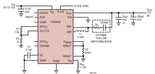
The LTM4609 is a highly integrated buck-boost converter that allows for efficient power conversion across a wide range of input and output voltages. The circuit is designed to maintain a stable output voltage of 12V regardless of variations in input voltage within the specified range. The efficiency of the circuit is enhanced by the use of a current mode control architecture, which provides improved transient response and stability during sudden changes in load conditions.
In the schematic, the LTM4609 is connected to a few essential passive components, including input and output capacitors, an inductor, and a feedback resistor network. The input capacitors are crucial for minimizing voltage ripple and ensuring stable operation, while the output capacitors help maintain the desired output voltage during load transients. The inductor is selected based on the desired current rating and inductance value, which affects the overall efficiency and performance of the converter.
The feedback resistor network is used to set the output voltage to the desired level of 12V. By selecting appropriate resistor values, the output voltage can be accurately adjusted within the range supported by the LTM4609. The device also features a synchronization pin, allowing it to be synchronized with an external clock signal. This capability is particularly useful in applications where multiple converters are used, as it helps to minimize electromagnetic interference (EMI) by reducing the generation of harmonic frequencies.
Overall, the LTM4609-based buck-boost converter is a versatile and efficient solution for applications requiring stable voltage regulation across varying input conditions, making it suitable for a wide range of electronic devices and systems.A very simple high efficiency switching mode buckboost power supply circuit can be designed using the LTM4609 switching regulator IC. This switching power supply circuit will provide an fixed output voltage of 12 volt. As you can see in the schematic circuit, this switching power supply circuit require few external electronic components.
LTM46 09 supports an operating input voltage range of 4. 5V to 36V and supports an output voltage range of 0. 8V to 34V, set by a resistor. This high efficiency design delivers up to 4A current in boost mode operation. The high switching frequency and current mode architecture enable a very fast transient response to line and load changes without sacrificing stability. The LTM4609 can be frequency synchronized with an external clock to reduce undesirable frequency harmonics.
🔗 External reference
Related Circuits
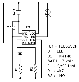
This circuit utilizes the TLC555CP timer integrated circuit to flash an LED approximately twice per second. This specific 555 timer operates on a voltage of only 3 volts, allowing it to be powered by two 1.5-volt cells. When using...
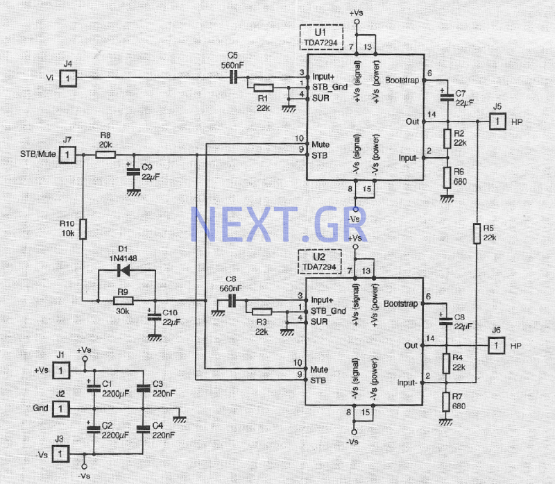
The TDA 7294 from T-MICROELECTRONICS is a monolithic integrated circuit housed in a "Multiwatt 15" package, primarily designed for use in Class AB amplifiers for high-fidelity applications, including stereo systems, active speakers, and television receivers. Its large feed area...
This circuit is designed to demonstrate high-frequency high voltage, capable of producing approximately 30 kV, depending on the transformer utilized. It is cost-effective and simple to construct, primarily using a standard TV flyback transformer. The circuit can power lasers,...
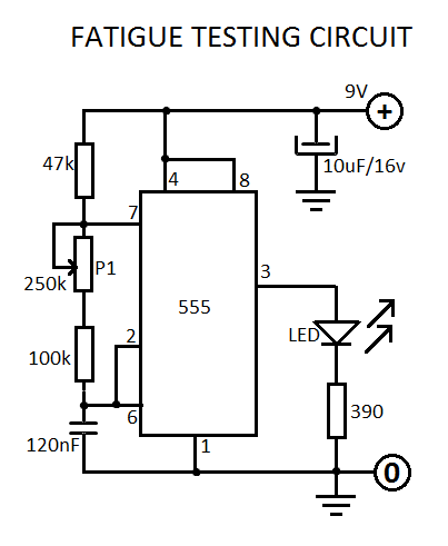
This fatigue testing circuit is straightforward and easy to assemble, designed to assess an individual's level of fatigue. Research indicates that the highest light frequency can be used as an indicator. This fatigue testing circuit operates on the principle of...
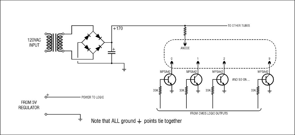
The high voltage supply will function, but for safety and to prevent accidental damage during troubleshooting with an oscilloscope, it is highly recommended to use an isolation transformer on the 120VAC input. A small 1:1 transformer rated at 30VA...
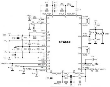
This is a stereo amplifier circuit diagram. The amplifier will produce stereo output channels with a power audio output that can reach up to 70W for each channel. The amplifier is built using the STA550 chip from STMicroelectronics. It...