
audible logic pulses

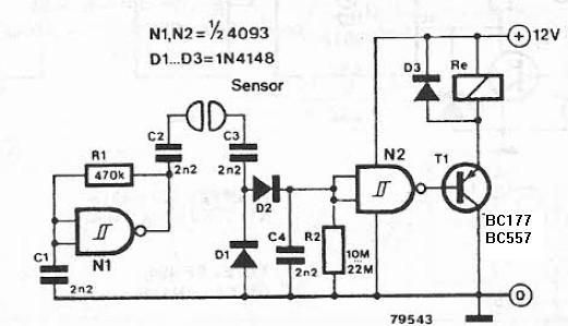
The described circuit utilizes a Schmitt trigger configured as an oscillator to monitor slow logic pulses effectively. It serves dual purposes: functioning as a keying monitor and acting as a digital clock alarm. The Schmitt trigger's inherent hysteresis provides stable switching characteristics, which are essential for distinguishing between high and low logic levels, particularly in slow pulse applications.
The circuit incorporates a trimpot (trimming potentiometer) that allows for precise adjustment of the output frequency or pitch. This feature is particularly useful in applications where specific timing or frequency characteristics are required. As the input signal transitions to a high state, the oscillator becomes activated, producing an oscillating output.
In terms of implementation, the Schmitt trigger is typically connected in a feedback configuration, which establishes the oscillation. The output frequency can be adjusted by varying the resistance of the trimpot, thus changing the charge and discharge times of the timing capacitor in the circuit. This adjustment enables fine-tuning of the oscillation period, allowing the circuit to adapt to different monitoring needs or alarm conditions.
Overall, this circuit design exemplifies a versatile approach to pulse monitoring, leveraging the reliable properties of the Schmitt trigger and the adjustable nature of the trimpot to meet various application requirements.This circuit is useful for monitoring slow logic pulses as a keying monitor or digital clock alarm. The Schmitt trigger is connected as an oscillator. The trimpot controls the pitch of the output. When the input goes high, the circuit will oscillate.
Related Circuits

This circuit diagram for a logic tutor kit was created using MS Word graphics. While modern software is commonly utilized, there may be instances where traditional methods are necessary. Employ a sharp pencil and a ruler to ensure precision;...
The liquid detector is a device designed to detect the presence of liquid using alternating voltage. This circuit can be constructed using common electronic components. The alternating voltage is generated by a gate with a Schmitt trigger function, acting...
Both specifications were contradictory; a large display would require a significant amount of power, while the intention was to use the smallest battery for the longest duration. The solution was to separate the power supply for the logic and...

The circuit, illustrated in Figure five, employs a tri-state logic pen audio circuit. It primarily consists of a multivibrator, a four-way switch (CD4066, IC1), and several RC components. The multivibrator (555, IC2), along with resistors R7, R8, R9 and...
This continuity tester circuit allows for the examination of PCB track failures without the need to visually inspect the routing of the tracks, which can often be frustrating. The continuity tester circuit is designed to facilitate the detection of faults...
Ideally, any testing equipment will not draw any current from the device under test. This ideal condition can be approximated by designing a testing device. To achieve the ideal condition where testing equipment does not draw current from the device...