
Five uses tri-state logic audio pen CD4066 555

The circuit utilizes a 555 timer configured in astable mode, which generates a continuous square wave output. This output is used to control the four-way switch (CD4066), allowing for the selection between different audio signals or pathways. The CD4066 is a quad bilateral switch that can connect or disconnect four independent signal paths, providing flexibility in routing audio signals based on the state of the multivibrator.
Resistors R7, R8, and R9, in conjunction with capacitor C1, determine the frequency and duty cycle of the oscillation produced by the 555 timer. The values of these components can be adjusted to set the desired operating frequency of the multivibrator, which directly influences the switching rate of the CD4066.
This tri-state logic pen audio circuit is particularly useful in applications requiring dynamic audio signal routing, such as in mixers or effects processors, where multiple audio sources need to be switched seamlessly. The integration of the multivibrator and the CD4066 allows for efficient control of audio pathways, enabling complex audio manipulation without the need for mechanical switches, thereby enhancing reliability and reducing wear over time.As shown in Figure five uses tri-state logic pen audio circuit. The circuit mainly by the multivibrator, four-way switch CD4066 (IC1) circuit with some RC com ponents consisting of other components. Wherein the multivibrator 555 (IC2) and R7, R8, R9, C1 constituted by the oscillation frequency off IC1-3 state control.
Related Circuits
This audio noise filter circuit functions as a bandpass filter specifically designed for the audio frequency range. It effectively filters out unwanted signals that fall below or above the desired audio frequencies. The circuit comprises two filters: a low-pass...
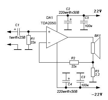
TDA2050 audio amplifier circuit diagram. The circuit incorporates environmental protection, where the output signal travels through connecting cables and the speaker’s network. In this case, the reactance of the circuit section connected to pin 4 of the chip is...
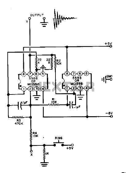
This simple bell circuit utilizes two 555 timers. The frequency is regulated by capacitors that should maintain nearly identical values for optimal performance. Fine-tuning is achieved using resistors R1 and R2. Additionally, the decay time is managed by resistor...
The LM3886 high-performance audio power amplifier circuit schematic is a crucial component in sound reproduction within audio systems. This audio power amplifier utilizes the LM3886 integrated circuit to enhance sound quality and output. The LM3886 is a high-performance audio power...
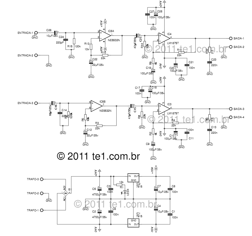
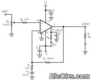
The LM1875 delivers 20 watts into a 4 or 8-ohm load on ±25V supplies. Using an 8-ohm load and ±30V supplies, over 30 watts of power may be delivered. The amplifier is designed to operate with a minimum of...
Designs for audio amplifiers with DC coupling to the load are not commonly seen today, despite their clear benefits. One advantage... Audio amplifiers utilizing DC coupling to the load present several notable advantages in specific applications. DC coupling allows for...