
Audible Transistor Tester

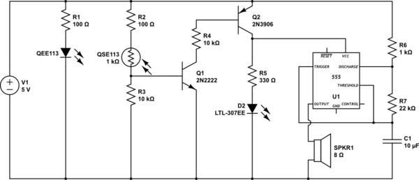
In this project, a comprehensive testing setup for various transistor types is established. The circuit is designed to accommodate different transistor configurations, including standard bipolar junction transistors (BJTs), Darlington pairs, and power transistors.
To initiate testing, a 9V battery is employed as the power source. It is important to note that the battery should be connected in reverse at designated points A and B. This reverse connection is a critical aspect of the testing procedure, as it allows for the evaluation of the transistors under non-standard conditions, which can reveal important characteristics such as breakdown voltages and reverse bias behavior.
The testing circuit will likely include key components such as resistors, which are used to limit current and protect the transistors during testing. A series of test points may be integrated into the schematic to facilitate easy measurement of voltages and currents at various stages of the circuit. Additionally, a multimeter can be employed to measure the collector-emitter voltage (Vce), base-emitter voltage (Vbe), and collector current (Ic) for each transistor type.
For Darlington transistors specifically, the circuit will demonstrate the high current gain characteristics, making it essential to observe the input and output relationships. Power transistors will be tested under higher load conditions to ensure they can handle the required power dissipation without failure.
Overall, the project aims to provide a thorough understanding of transistor behavior across different configurations and operating conditions, contributing to the knowledge base of electronic circuit design and analysis.All types of transistors including Darlington and power will be tested in this project. Connect the 9v battery around the other way at points A and B to test.. 🔗 External reference
Related Circuits
The microphone has high sensitivity in the audio range, but in the ultrasonic range, the sensitivity decreases rapidly. The receiver is very sensitive. To prevent overdriving and feedback due to the high sensitivity of the microphone in the audio...
This circuit detects when a tube is empty and pulses a piezo buzzer at 5-second intervals. It is currently operational with a 5V supply on a breadboard but needs to be adapted for a 12V supply from a wall...
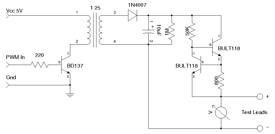
A simple Zener diode tester circuit, when combined with a PWM generator, can be utilized to measure the breakdown voltage of Zener diodes. More generally, it can also measure the breakdown voltages (e.g., BVceo, BVcbo) of BJTs (Bipolar Junction...
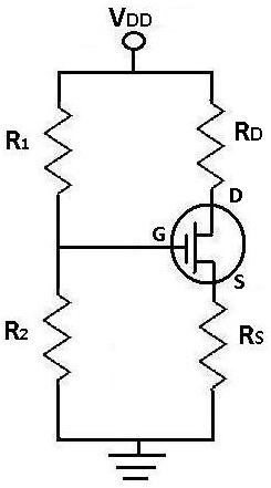
During DC analysis, all AC voltage sources are removed from the circuit since they are AC sources. DC analysis focuses solely on DC sources. Additionally, all capacitors are removed because, in a DC context, capacitors act as open circuits....
This is a variation on the astable multivibrator. Circuit was recently developed to test for N-mosfets (the power kind e.g. irf830). I don't claim circuit can test all bad mosfets or all fault mosfet conditions. If mosfet is working...
I have not transitioned from the Z80 camp to the CNC/Fabber camp. Although there have not been any updates on the Z80 for a considerable time, updates will be forthcoming. The construction of the CNC machine is still some...