
All transistor microphone pre-amplifier

The circuit described involves a microphone system that exhibits high sensitivity to audio frequencies, yet its sensitivity diminishes significantly at ultrasonic frequencies. The microphone's output is fed into an amplifier designed to manage this sensitivity effectively. The amplifier must be configured to maintain low gain in the audio range to prevent overdriving and feedback, which can occur due to the microphone's high sensitivity.
The gain characteristics of the amplifier are critical; at 10 kHz, the gain is set to 6 dB, which is relatively low and suitable for audio applications. As the frequency increases to 20 kHz, the gain rises to 24 dB, indicating an increase in amplification that compensates for the microphone's decreasing sensitivity in the ultrasonic range. At 100 kHz, the gain reaches 50 dB, reflecting the design's intent to enhance the signal from the microphone in the ultrasonic spectrum while managing noise levels effectively.
To achieve optimal performance, the intrinsic noise of the amplifier should be minimized, ensuring that the signal-to-noise ratio remains favorable across the frequency range of interest. This design consideration is crucial for applications requiring precise audio and ultrasonic signal processing. The amplifier's frequency response must be carefully tailored to ensure smooth gain transition from audio to ultrasonic frequencies, preventing any abrupt changes that could introduce distortion or artifacts in the output signal.
Overall, the design emphasizes a balance between sensitivity management and noise reduction, making it suitable for applications that require reliable performance across a broad frequency spectrum.The microphone has high sensitivity in the audio range, but in the ultrasonic range, the sensitivity decreases rapidly. The receiver is very sensitive. To prevent overdriving and feedback due to the high sensitivity of the microphone in the audio range, the gain of the amplifier should be low in the audio range and increase with frequency in the ultrasonic range.
The intrinsic noise of the amplifier should be as low as possible. The amplifier below satifies this requirement: The gain at 10 kHz is: 6 dB, at 20 kHz: 24 dB and at 100 kHz: 50 dB. 🔗 External reference
Related Circuits
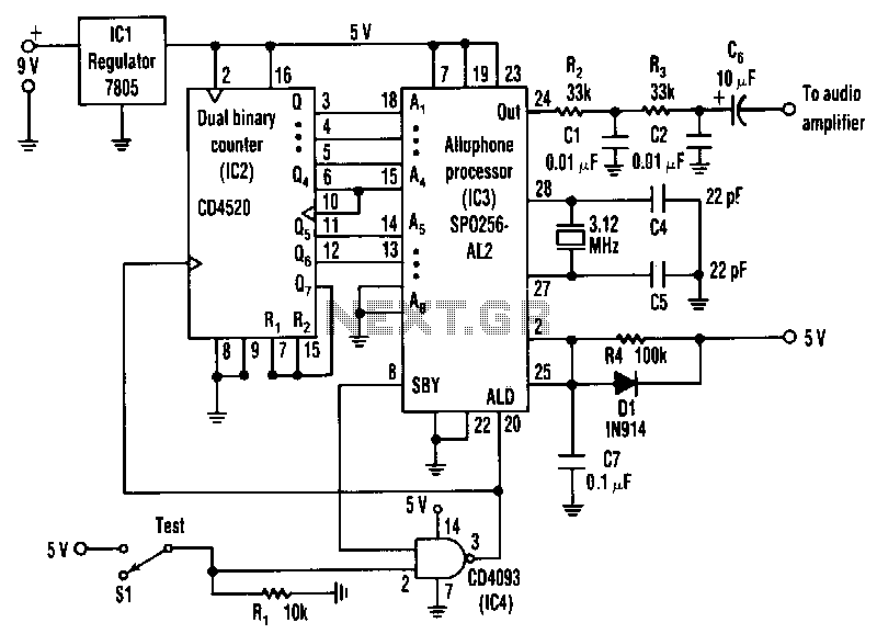
The circuit is a general-purpose system with various applications that vocalizes 59 allophones stored in the speech processor. After filtering and amplification, its pulse-code-modulated output can drive an 8-ohm speaker. The address pins of the processor, labeled A1 to...
This is the basic FM transmitter that I built. In theory, according to electronics, it shouldn't work but works fine and is very sensitive. It can transmit the signal up to 45 yards (about 40 meters). A sensitive FM...
Both circuits can synchronize trapezoidal wave voltage, which is converted into intermittent small rectangular pulses. Its working principle involves periodic operation in synchronization with the grid frequency of the zero-volt switching voltage of the DC chopper. Due to the...
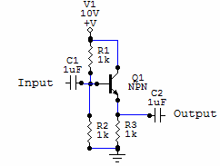
Two examples of the most common types of Voltage followers (buffers). You can find some theory behind them in our amplifier gain and buffer amplifier pages. This first circuit is a very simple one transistor voltage follower. Consists of...
Electric motors have been widely used for motion control, and various types of motor controllers have been designed to provide variable speed drives for these motors. Electric motors are integral to numerous applications requiring precise motion control, ranging from industrial...
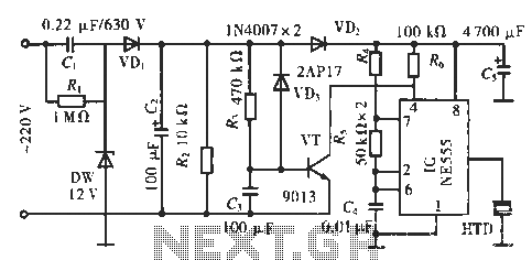
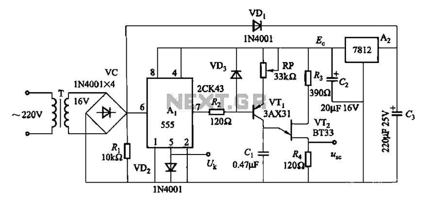
The circuit utilizes a 555 integrated circuit (IC). When an incoming call is received, 220 V AC is stepped down through resistor R1, followed by rectification using diode VD1. A voltage regulator (DW) is employed, and capacitor C2 is...