
Audio Amplifier Volume Indicator

The described circuit functions as a volume indicator for audio systems, employing a static design to prevent audio interference. The use of differentiating networks R9/C1 and R10/C2 serves a critical role in converting LSB changes into a usable clock signal, effectively doubling the frequency to enhance responsiveness. This ensures that the indicator can rapidly reflect changes in volume without introducing noise into the audio path.
The integration of "up/down" and "preset" signals from the preamplifier allows for a seamless interaction between the indicator and the audio control system. This design choice optimizes the circuit layout by reducing the number of connections, which can improve reliability and reduce potential points of failure.
The choice of using 8-bit BCD for the present counters, as opposed to the 6-bit binary format from the volume control, allows for a more straightforward display of the volume level. The BCD-to-7-segment decoders convert the binary-coded decimal into a format suitable for visual representation on 7-segment displays, providing clear and immediate feedback to the user.
The requirement for the preset to be in BCD code ensures that the system can accommodate a range of volume settings, and the display of leading zeros allows for a consistent visual format, enhancing user experience. The option to replace DIP switches and resistors with jump leads simplifies the design for applications where a single preset is sufficient, further streamlining the circuit.
Overall, this circuit design exemplifies an effective solution for integrating visual indicators into audio systems, balancing functionality with simplicity while ensuring high performance in tracking volume changes. The indicator is intended for use with an audio amplifier or preamplifier, but it can also be used in othe r applications where a number of steps or changes must be counted rapidly. To prevent interference with the audio signal, the circuit is a static design. Thus, if the volume control is not adjusted, the circuit does nothing. The circuit does not need an external clock signal, because this is derived from any changes in the least significant bit (LSB). This is done by two differentiating networks: R9/C1 and R10/C2, which double the frequency of an available LSB signal.
Moreover, to ensure that the counters of the indicator remain in step with the volume control, signals "up/down" and "preset" from the preamplifier are used. It might seem rather extravagant to couple the state of the counters in the preamplifier with that of the present counters, but it is a good way to keep the connections between the two units to a minimum.
Furthermore, the present counters operate in 8-bit BCD, instead of 6-bit binary as used by those in the volume control (in the preamplifier). All that is required to display the state of the volume control are a couple of BCD-to-7-segment decoders and 7-segment displays.
The preset in the indicator must be set in BCD code. Leading zeros are not suppressed so numbers up to and including 9 are displayed, starting with a 0. The DIP switches and resistors Rl through R8 in the diagram can be omitted if only one fixed preset is likely to be used. The resistors should be replaced by jump leads.
Related Circuits

Audio Graphic Equalizer. Audio graphic equalizers are widely used as commercial products in high-fidelity systems, car audio, and stage applications; however, circuits for these devices are seldom published. Audio graphic equalizers are essential tools in audio processing, allowing users to...
In personal electronics and computer audio systems, the SSM2167 is a complete and flexible solution for conditioning microphone inputs. It is also very good for various applications. The SSM2167 is an integrated circuit specifically designed for microphone preamplification and audio...
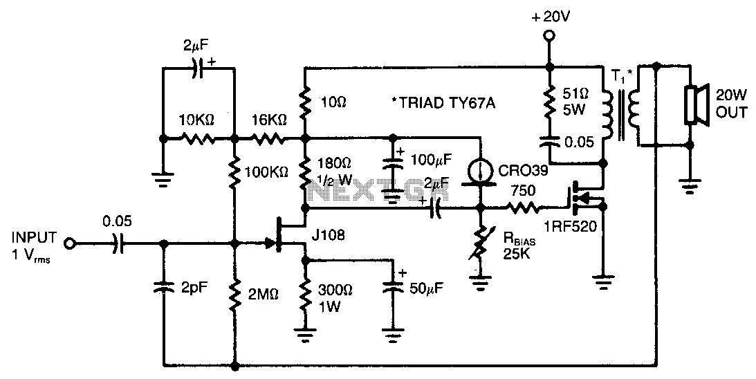
This amplifier provides 20 W of power to an 8-ohm load utilizing a single IRF520 transistor driving a transformer-coupled output stage. The design resembles the audio output stages commonly found in many low-cost radios and phonographs. Distortion remains below...
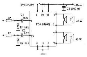
This car audio amplifier provides an output of 40 watts when connected to a 2-ohm speaker. The amplifier circuit delivers a power output of 40 watts per channel at a 2-ohm load and 22 watts at a 4-ohm load....
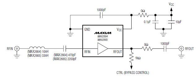
A simple, low-cost, and ultra-compact VHF/UHF low-noise amplifier circuit can be designed using the MAX2664 and MAX2665 ultra-compact LNAs for VHF/UHF applications. These devices incorporate a broadband LNA with an integrated bypass switch. The MAX2664 covers the UHF frequency...
A VOX is a voice-operated switch that is often used as a substitute for the press-to-talk switch on a microphone. This VOX can be connected to almost any audio equipment that has a socket for an external loudspeaker. The...