
Simple Audio-Frequency Vco

The VOX circuit operates as an effective voice-activated switch, replacing the need for manual operation in communication systems. The input from the microphone is processed through an audio frequency (AF) amplifier, which adjusts the sensitivity of the VOX according to the volume control setting. The audio signal is routed to a resistor (R2), where it is capacitively coupled to the base of transistor T1. This configuration allows the VOX to respond to the audio signal, enabling the switch to actuate when the signal level exceeds the defined threshold of 600 mV.
Transistor T1 plays a critical role in controlling the base current to T2, which is configured as a Darlington pair to drive the output relay. Resistor R3 ensures that the base current remains within safe limits, preventing damage to T1 when input signals exceed the threshold. Diode D1 serves as a protective element, preventing negative voltage swings that could adversely affect the operation of T1 by clamping the voltage to approximately 0.6 V.
The relay, controlled by T2, allows for the switching of higher power loads, making the VOX suitable for various audio equipment applications. Resistor R4 is strategically placed to keep the relay in a non-activated state when T1 is off, preventing unwanted triggering of the relay. The design incorporates a bipolar capacitor (C2) that functions as a ripple filter, smoothing out any fluctuations in the output signal from T2, ensuring stable operation of the relay.
The overall input voltage to the VOX should not exceed 40 Vpp, as dictated by the power ratings of resistors R2 and R3. The circuit is designed to handle a maximum current draw of 100 mA, which includes the current through the relay coil and resistor R5. This ensures that the VOX operates efficiently without overheating or damaging components during overdrive conditions. This VOX design is versatile and can be integrated into various audio systems, enhancing user experience by automating the switching process based on voice activation. A VOX is a voice-operated switch that is often used as a substitute for the press-to-talk switch on" a microphon e. This VOX can be connected to almost any audio equipment that has a socket for an external loudspeaker. The actuation threshold is set by the volume control on the AF amplifier that drives the VOX. The (loudspeaker) signal across R2 is capacitively fed to the base of Tl. Resistor R3 limits the base current of this transistor when the input voltage exceeds 600 mV. Diode Dl blocks the positive excursions of the input signal, so that Veb cannot become more negative than about 0.6 V.
The output relay is driven by Darlington T2. Resistor R4 keeps the relay disabled when Tl is off. The value of bipolar capacitor C2 allows it to serve as a ripple filter in conjunction with T2. Resistor R5 limits the base current of 2 to a safe level. The switching threshold of the VOX is about 600 mV across R2. The maximum input voltage is determined by the maximum permissible dissipation of R2 and R3. As a general rule, the input voltage should not exceed 40 Vpp. The current drawn by the VOX is mainly the sum of the currents through the relay coil and through R5. The resistor can carry up to 100 mA when the VOX is overdriven.
Related Circuits
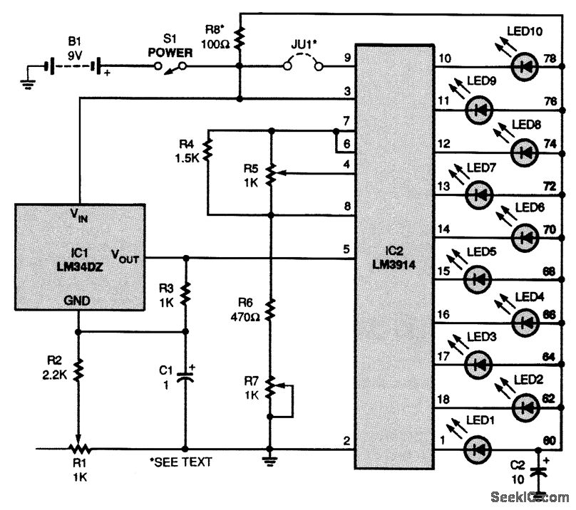
The circuit is powered by a 9-V battery (B1) but can also operate with any 7- to 10-V DC power supply. At the core of the thermometer is IC1, an LM34 temperature sensor, which generates a voltage between the...
This circuit utilizes the widely available LM3914 integrated circuit (IC), which is straightforward to operate and does not require external voltage regulators due to its built-in voltage regulation capabilities. It can be powered from various sources. When the test...
A simple variable frequency oscillator utilizing a 555 timer IC to generate a square wave frequency that can be adjusted using a potentiometer. The circuit operates primarily on the principles of astable multivibrator configuration using the 555 timer IC, which...

The ongoing debate regarding the superiority of valves versus transistors is not the focus here. However, for those undecided, this simple amplifier serves as an excellent test. It employs a valve as a pre-amplifier and a MOSFET in the...
If you have a servo and you want to test it but do not have a remote control or a dedicated tester, you can create a simple schematic for a servo tester. This circuit is based on a 555...
This simple and inexpensive crystal oscillator consists of one-third of a 7404 hex inverter, four resistors, and a crystal. The inverters are biased into their linear regions by resistors R1 to R4, while the crystal provides the necessary feedback....