
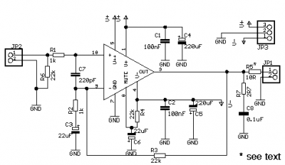
Schematic Diagram VHF UHF Low-Noise amplifier circuit

The circuit utilizes the MAX2664 and MAX2665 as the core components, which are designed to amplify weak radio frequency signals while minimizing noise. The MAX2664 is optimized for UHF applications, making it ideal for television and radio frequencies, while the MAX2665 is tailored for VHF applications, suitable for FM radio and other communication systems.
The low-noise amplifiers are configured in a common-source configuration, which provides significant voltage gain and a broad bandwidth. The integrated bypass switch allows the circuit to enter a low-power state when high signal levels are detected, effectively reducing power consumption during idle times. This feature is particularly beneficial in battery-operated devices where energy efficiency is critical.
External components required for the circuit are minimal, typically including a few resistors and capacitors for biasing and stability. The design can be easily integrated into compact PCB layouts, making it suitable for portable applications. The power supply requirements are flexible, allowing for operation from batteries or regulated power sources, which is advantageous for mobile devices.
The low current consumption of 3.3 mA ensures that the amplifiers can operate efficiently without significantly draining the battery, which is essential for devices such as smartphones and portable media players. The high gain of around 15 dB ensures that even weak signals can be amplified sufficiently for further processing, enhancing the overall performance of the system.
Overall, the MAX2664 and MAX2665 low-noise amplifiers present an effective solution for enhancing signal quality in VHF and UHF applications, making them a valuable addition to a wide range of electronic devices.A very simple low cost and ultra compact VHF UHF Low-Noise amplifiers circuit can be designed using the MAX2664 and MAX2665 ultra-compact LNAs for VHF/UHF applications. These devices incorporate a broadband LNA with an integrated bypass switch. The MAX2664 covers the UHF frequency range from 470MHz to 860MHz, and the MAX2665 covers the VHF frequen
cy range from 75MHz to 230MHz. Each device has a zero-power bypass mode for improved high-signal-level handling conditions. As you can see in the presented circuit diagram, this RF project requires very few external components. Both ICs has a high gain around 15dB and require a single power supply, that can provide an output voltage between 2.
4 to 3. 5 volts. VHF UHF Low-Noise amplifiers has a very low current consumption of 3. 3 mA and can be used in applications like: Smartphones/Handsets, MP3 Players, Home Audio/Video and other portable navigation devices. 🔗 External reference
Related Circuits
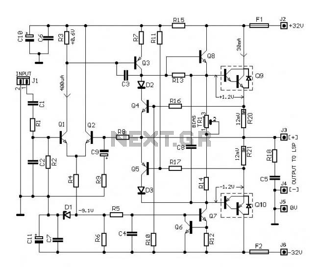
The circuit of this 30W audio amplifier produces clear audio output quality. The circuit module does not have any improvements. It utilizes a Darlington pair in the transistor configuration. The 30W audio amplifier circuit is designed to deliver high-fidelity sound...
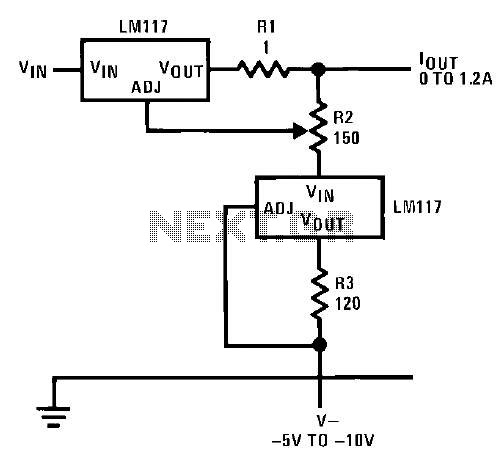
This circuit illustrates an adjustable regulator configuration that incorporates a voltage regulator. In this design, the LM117 regulator is utilized instead of the LM113 diode for reference. Both regulators necessitate a negative supply to function correctly with respect to...
This circuit consists of two main components: a battery charger that provides a fixed output voltage of 5V DC, and a regulated power supply that allows for an adjustable output voltage ranging from 2 to 9 volts. The circuit design...
A general purpose audio power amplifier is a must have for the electronics amateur. It's not a good thing to use your HiFi set for an experiment, when there's a risk of blowing its transistor out. Amplifier for your...
The following circuit illustrates a Mains Remote-Alert Circuit Diagram. Features include simple circuitry, with the transmitted signal being conveyed effectively. The Mains Remote-Alert Circuit is designed to provide a notification system that alerts users about the status of mains power....
The following circuit illustrates a UHF Indicator Wavemeter Circuit Diagram. This circuit utilizes dual BF494 transistors. Features: the oscillator is... The UHF Indicator Wavemeter Circuit is designed to measure and indicate the frequency of ultra-high frequency (UHF) signals. The circuit...