
Audio Amplifiers

This circuit design focuses on the implementation of a high-gain audio amplifier using the LM386 integrated circuit, which is optimized for low-power applications. The choice of components and configuration is critical to achieving the desired performance specifications. The LM386 is configured for a gain of 200, suitable for amplifying weak audio signals, while providing flexibility through the use of a variable gain potentiometer.
The use of the 2SK117 JFET in the Curiously Low Noise Amplifier enhances the circuit's performance by minimizing noise, which is particularly important in sensitive applications such as laboratory measurements. The design integrates a feedback mechanism to stabilize gain and ensure linear performance across varying load conditions. The choice of metal film resistors is intentional, as they offer superior noise characteristics compared to standard carbon film resistors.
The circuit's output stage includes provisions for driving low-impedance loads, with careful attention to the selection of the output resistor to maintain stability and prevent oscillations. The design also emphasizes the importance of power supply decoupling to mitigate noise, particularly when operating with potentially unstable supply voltages.
Overall, this amplifier circuit exemplifies a balance between simplicity and performance, making it suitable for a wide range of audio applications where low noise and high gain are essential. The detailed attention to component selection and circuit topology ensures that it can effectively handle the amplification of small signals while maintaining fidelity and stability.The first choice is usually an integrated circuit designed for the purpose. A typical assortment can be seen on this National Semiconductor page. Discrete designs can also be built with readily available transistors or op-amps andmany designs are featured in manufacturers` application notes. Older designs employed audio interstage and output transformers but the cost and size of these parts has made them all but disappear. (Actually, when the power source is a 9 volt battery, a push-pull output stage using a 500 ohm to 8 ohm transformer is more efficient than non-transformer designs when providing 100 milliwatts of audio. ) As a general rule, transformerless low power speaker projects will work better with 4. 5 or 6 volt battery packs of AA, C, or even D cells than 9 volt rectangulars. This simple amplifier shows the LM386 in a high-gain configuration (A = 200). For a maximum gain of only 20, leave out the 10 uF connected from pin 1 to pin 8. Maximum gains between 20 and 200 may be realized by adding a selected resistor in series with the same 10 uF capacitor.
The 10k potentiometer will give the amplifier a variable gain from zero up to the maximum. The Curiously Low Noise Amplifier takes advantage of the wonderful noise characteristics of the 2SK117 JFET that boasts a noise voltage below 1 nV/root-Hz and virtually no noise current. The noise voltage of the amplifier is only 1. 4 nV/root-Hz at 1 kHz, increasing to only 2. 7 nV/root-Hz at 10 Hz. The noise current is difficult to measure, so this simple utility amplifier can see the noise from a 50 ohm resistor and a 100k resistor, too.
(The 1. 4 nV input-referred noise will increase to about 1. 7 nV with a 50 ohm resistor, instead of a short, and a 100k resistor will give an input-referred noise near 40 nV, with very little contribution from the amplifier. ) This amplifier is a "utility" amplifier with a gain of 100, that would typically be used in a lab setting to boost tiny signals for measurement or further processing.
It isn`t intended to drive a speaker or headphones directly. (It could drive the LM386 quite nicely. ) The circuit is a simple discrete transistor feedback circuit with two gain stages and a unique class-A output buffer: The 2sk117 is from the "BL" Idss current range and is selected for an Idss near 7 mA. The drain resistor is adjusted to achieve about 4 volts on the drain and the value depends on the Idss of the JFET.
Most of the resistors aren`t critical, but precision values are shown because the resistors should be metal film types for best noise performance. Approximate DC voltages are shown for helping with resistor selection. Deviating from the shown voltages will reduce the available output voltage swing, but the amplifier might work fine for smaller signals.
Unloaded swing should be about 6 volts, p-p with about 60 mV p-p input, before distortion is observed. The MPSA18 acts as a noise filter. High gain is desirable here to keep the value of the base filter capacitor reasonable, but a 2N4401 could be substituted by reducing the 10k and 120k by a factor of 5.
The filter will still be rolling off the noise voltage from the 15 volts supply above about 0. 2 Hz. But some power supplies can be really noisy! The feedback resistor is selected for a gain of exactly 100 and the value is well above the expected 1k, due to the limited open-loop gain of the simple circuit. A small resistor is included in series with the output for stability and that resistor can reduce the gain a bit when driving a lower resistance load.
The designer may choose to set the gain for that particular load, say 75 ohms, or for a high impedance load. The circuit can drive a lower resistance than 100 ohms, but the swing will be somewhat limited. It may be possible to leave out the 33 ohm resistor without sta 🔗 External reference
Related Circuits
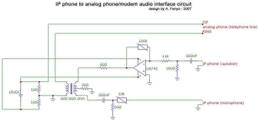
The transformer is a 600:600 ohm transformer, also referred to as a 1:1 ratio 600 ohm transformer. It has approximately the same number of turns on both the primary and secondary coils and is optimized for operation at a...
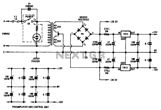
A dual audio amplifier that delivers 50 W per channel is illustrated in the schematic. It features a preamplifier and tone controls, as well as a headphone amplifier. The circuit also shows a power supply providing 38.5 V and...
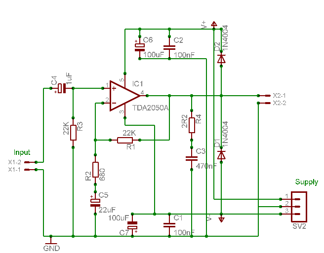
A careful examination of the amplifier photos reveals that the heatsink on the HY60 near-clone built using the TDA2050A is slightly shorter than that of the original HY60s. This unit is positioned at the rear of the amplifier, creating...
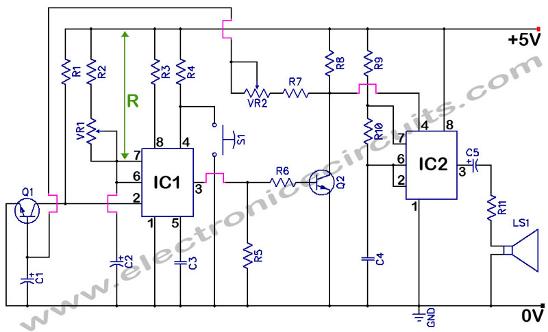
555 Timer with Audio Alarm Circuit. This circuit serves as a straightforward electronic timer equipped with an audio alarm feature. The 555 timer is a versatile integrated circuit widely used in various timer, delay, pulse generation, and oscillator applications. In...
A peak level indicator when a signal exceeds a certain maximum value. It can be quite useful, for instance, with tape recorders, mixing consoles etc. One of the most important requirements of a peak level indicator is that it...
High-end audio equipment is typically controlled digitally by a microprocessor (microcontroller) system. It is necessary to have a digital interface that allows for effective communication and control. High-end audio systems utilize a microcontroller to manage various functionalities, enabling precise control...