
555 Timer With Audio Alarm Circuit

The 555 timer is a versatile integrated circuit widely used in various timer, delay, pulse generation, and oscillator applications. In this specific circuit configuration, the 555 timer operates in astable mode, generating a square wave output that can be used to trigger an audio alarm.
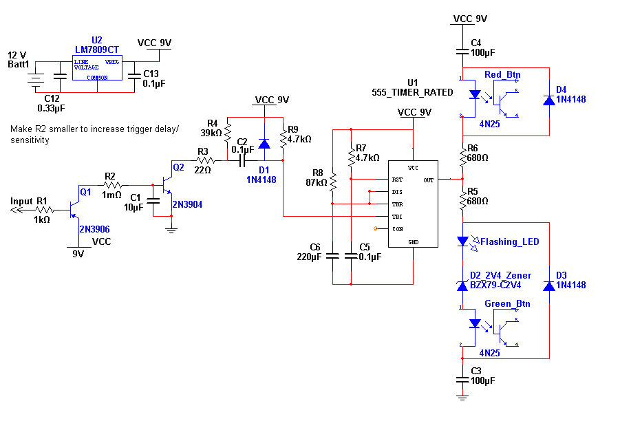
The circuit typically consists of a 555 timer IC, resistors, capacitors, and a speaker or buzzer. The resistors (R1 and R2) and capacitor (C1) determine the timing intervals, which can be adjusted to set the duration of the audio alarm. The output pin (Pin 3) of the 555 timer is connected to the audio device, which can be a simple piezo buzzer or a small speaker, allowing the circuit to produce sound when triggered.
When power is applied, the 555 timer begins oscillating, creating a continuous output that activates the audio device. The frequency of the oscillation can be calculated using the formula:
\[ f = \frac{1.44}{(R1 + 2R2) \cdot C1} \]
This frequency determines the pitch of the sound produced. The duty cycle, which is the ratio of the time the output is high to the total time period, can also be adjusted by varying the resistor values.
To ensure the circuit operates effectively, proper power supply considerations should be made, typically utilizing a 5V to 15V DC source. Additionally, bypass capacitors may be included to stabilize the power supply and reduce noise in the output signal.
This simple yet effective circuit can be utilized in various applications, such as alarm systems, timers for cooking, or reminders for tasks, making it a valuable addition to any electronics project.555 Timer With Audio Alarm Circuit Here is a very simple circuit for electronic timer with audio alarm. With the help of this circuit, audio.. 🔗 External reference
Related Circuits
VU (Volume Unit) meters used to be the mainstay of audio metering systems, but they have been replaced by LED metering in a great many mixers and other applications. Even in software, the most common level meter is made...
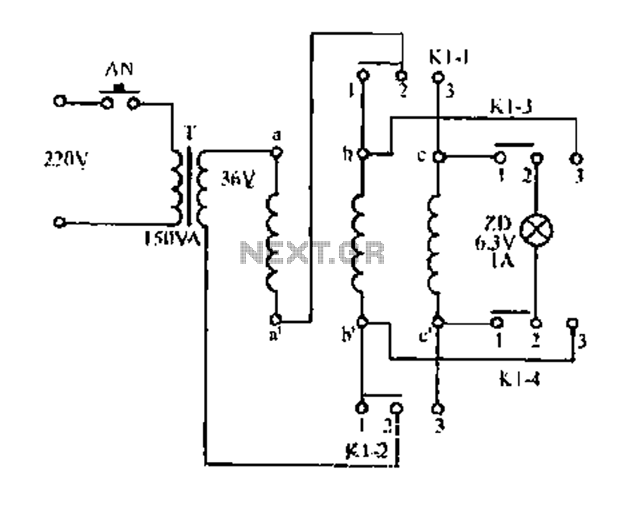
Figure aa, bb, and ce represent three-phase windings. A double throw switch Kl-1 to Kl-4 is positioned on the left side, connecting phases 1 and 2. At this point, aa and bb are in series with the secondary of...
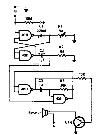
The timer can be utilized for time intervals of up to seven minutes. Activation is achieved by touching the turn-on plate, after which an alarm will sound for a brief duration upon the completion of the selected time, followed...
Figure 1 illustrates an AND gate logic circuit with the logic expression P=A. Figure B depicts two photodiodes connected in series. When the input logic levels A=1 and B=1, the output P=1. Similarly, this configuration can be used to...

When the protective circuit is interrupted (opened), the alarm sounds. To set the circuit, adjust R2 (with the protective circuit open) for 1 V across R1. The described circuit functions as a protective alarm system that activates when the integrity...
This entry is for the international 555 Contest. The 555 timer chip has been in use for many years and is highly versatile. The concept of this project addresses the need for notification of an event while away from...