
Audio Controlled Switch Circuit

The audio-controlled switch circuit is designed to respond to audio signals, allowing it to activate various devices based on sound input. The core of the circuit consists of two 741 operational amplifiers configured as a comparator. The first op-amp is used to amplify the audio signal, while the second op-amp compares the amplified signal to a predetermined threshold level. If the audio signal exceeds this threshold, the output of the second op-amp transitions from low to high.
This high output from the second op-amp is used to drive the base of the first 2N2222 transistor, which acts as a switch. When the transistor is activated, it allows current to flow from the power supply to the gate of the hexFET. The hexFET, being a type of MOSFET, is controlled by the voltage at its gate and can handle higher power loads, making it suitable for driving larger devices like tape recorders or transmitters.
The second 2N2222 transistor serves as a buffer, ensuring that the op-amp output can effectively drive the gate of the hexFET without loading down the op-amp circuit. Additional supporting components, such as resistors and capacitors, are included to stabilize the circuit and filter any noise from the audio signal. A diode may also be used to protect the circuit from back EMF generated by inductive loads.
Overall, this audio-controlled switch circuit provides a versatile solution for sound-activated applications, enabling users to control a wide range of devices with audio signals. Proper component selection and configuration are essential to ensure reliable operation and responsiveness to audio inputs. The audio-controlled switch combines a pair of 741 op amps, two 2N2222 general-purpose transistors, a hexFET, and a few support components to a circuit that can be used to turn on a tape recorder, a transmitter, or just about anything that uses sound.
Related Circuits
This works with a small geleidingstestertje LM 3909. It allows a tester beeps when the resistance between the probes between 0 and 100 ? lies. Due to the volume of the beep, the resistance between the probes can be...
This system is designed to communicate or transmit a text message from one location to another using a wireless circuit. The text message is encrypted with a microcontroller, and the encrypted message is transmitted wirelessly. At the receiving end,...
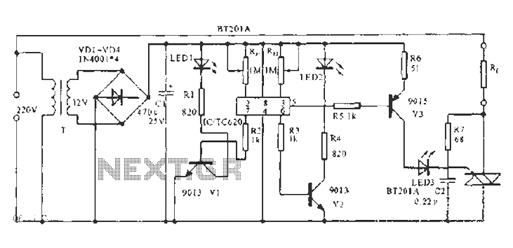
The built-in temperature sensor is utilized to control the triac TC620 for temperature regulation. The adjustment circuit, consisting of resistors Rp1 and Rn, allows for modifications to the lower temperature limit. When the ambient temperature exceeds this lower limit,...
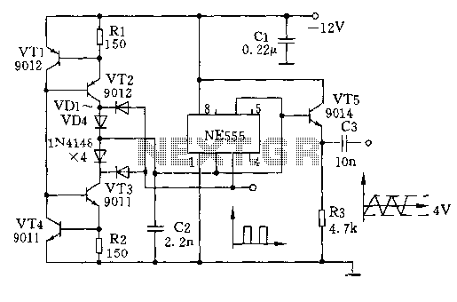
The circuit depicted involves transistors VT1, VT2, and resistor R1, which form a constant current source for charging capacitor C2 in a linear manner. Transistors VT3, VT4, and resistor R2 create a constant current source for discharging capacitor C2,...
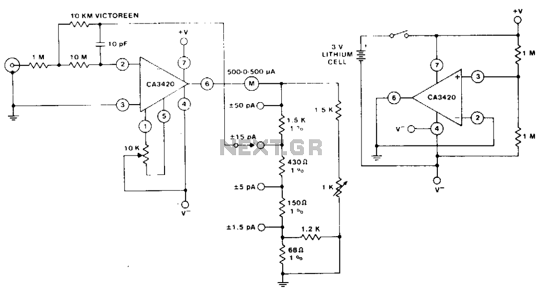
The circuit utilizes the extremely low input current (0.1 pA) of the CA3420 BiMOS operational amplifier. With only one 10 megohm resistor, it achieves a range from ±50 pA maximum to a full-scale sensitivity of ±1.5 pA. Additionally, by...
Observing my Boss pedals and how they were switched on and off I figured there must be more to it. It took me only about 4 hours to design and test this circuit. It works very well and I’m...