
Thermostat controller integrated circuit schematic

The circuit employs a temperature sensor that interfaces with the triac TC620 to manage heating or cooling systems effectively. The temperature sensor continuously monitors the ambient temperature and provides feedback to the control circuit. The adjustment circuit, which includes variable resistors Rp1 and Rn, allows users to set specific temperature thresholds. By altering these resistors, the lower temperature limit can be adjusted to meet specific operational needs.
LED indicators are integrated into the circuit for immediate visual feedback. LED1 serves as a status indicator for when the ambient temperature falls below the defined lower limit, signaling that heating may be required. LED2 functions similarly, indicating when the temperature exceeds the upper limit, which may suggest the need for cooling or a reduction in heating.
The choice of triac BCR is critical as it must be rated appropriately to handle the load's power requirements. This ensures reliable operation without risk of failure due to overcurrent conditions. The triac's gate can be triggered by the control logic derived from the temperature sensor output, allowing for precise control over the connected load. Overall, the design aims to maintain a stable temperature environment while providing clear visual indicators of the system's status.As shown in Figure by the built-in temperature sensor to control the triac TC620 achieve .png">temperature control . Adjustment circuit Rp1 and Rn can be changed each point and the lower temperature limit temperature point, LED1 lights to indicate that the ambient temperature exceeds the lower limit of temperature control point, LED2 lights to indicate that the ambient temperature exceeds the upper limit of temperature points. Triac BCR rated current selection can actually be charged according to the size of the load power. .png">
Related Circuits
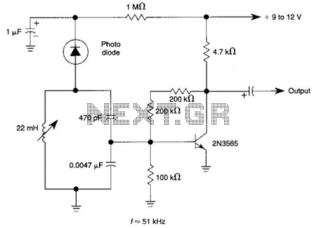
The circuit utilizes a tuned circuit for frequency selection, designed to operate at approximately 51 kHz. The 2N3565 transistor amplifies the output generated by the tuned circuit. The described circuit operates on the principle of resonance, where the tuned circuit...
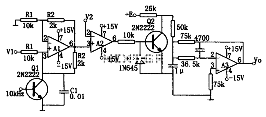
As illustrated in the dividing circuit diagram, A1 consists of a voltage-controlled current source, A2 functions as a voltage comparator, and A3 is configured as an active low-pass filter. When the time constant R1C1 is equal to the clock...
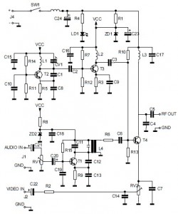
This is the circuit diagram of an audio/video modulator. The circuit converts audio and video signals into a UHF TV signal. It is designed to connect a video signal originating from a camera or other video source to a...
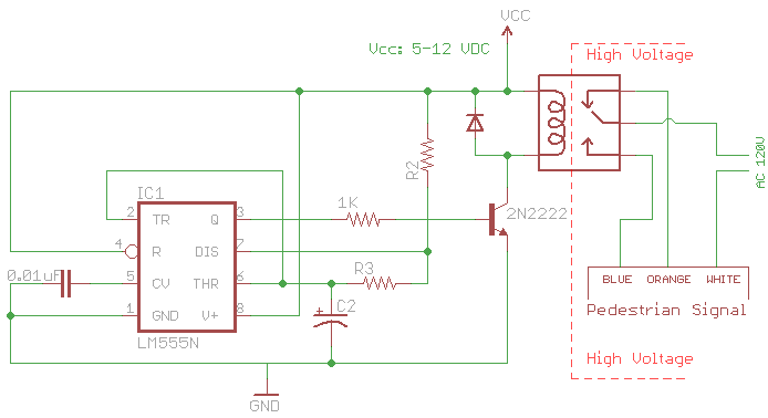
The signal consists of three wires: common, "walk," and "don't walk." This document outlines the operation of the unit's countdown feature. The information and examples provided here are applicable to other models and brands of signals. The signal was...

The Electro Harmonix Big Muff Pi circuit would likely benefit from the incorporation of a modern input-jack power connection and a DPDT bypass switch. The specific types of transistors and diodes used in the circuit are not specified. It...
Figure 15-22 illustrates a doorbell system that consists of a monostable timing circuit, a password switch, a NAND gate circuit, and a sound output circuit. The operation of the circuit is designed such that when the password switch is...