
Cookers pot quality detection circuit

The cookers pot quality detection circuit employs a method based on the measurement of electromotive force (EMF) generated by a disc lesion. This approach is predicated on the principle that the quality of the cooking pot can influence the electrical characteristics of the induced voltage. The circuit typically consists of a voltage sensing unit, which captures the EMF produced when a specific stimulus is applied to the pot.
The primary components of the circuit include a voltage comparator, which compares the measured voltage against a predefined threshold level. If the induced voltage exceeds this threshold, it indicates that the pot meets the quality standards. Conversely, if the voltage is below the threshold, the pot may be deemed substandard.
Additionally, the circuit may integrate a microcontroller for enhanced functionality, allowing for data logging and analysis of the quality test results. This microcontroller can also provide user feedback through an LCD display or LEDs, indicating whether the pot passes or fails the quality test.
Power supply considerations are crucial for the operation of the circuit. A stable voltage source is required to ensure accurate measurements. The circuit should also incorporate appropriate filtering to minimize noise and improve measurement reliability.
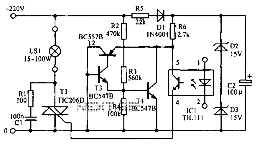
Overall, the cookers pot quality detection circuit serves as an effective tool for manufacturers and consumers alike, ensuring that only high-quality cooking pots are used in food preparation.Cookers pot quality detection circuit Shown as cookers pot quality detection circuit. Pot quality testing is by disc lesion induced voltage (EMF) to achieve.
Related Circuits
PWM waveforms are frequently employed to regulate the speed of DC motors. The mark/space ratio of the digital waveform can be established either by utilizing an adjustable analog voltage level (as seen in a NE555-based PWM generator) or through...
The circuit diagram illustrates the LED signal amplification. The LED signal amplification circuit is designed to enhance the output signal from an LED, allowing it to drive larger loads or to be interfaced with other electronic components effectively. The primary...
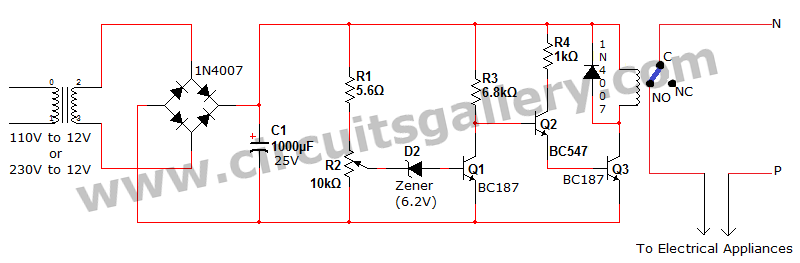
Voltage fluctuation is a significant concern in residential settings. For various reasons, the supply voltage may exceed 110V or 230V. This excessive voltage can potentially damage household electrical devices. An effective solution for electrical protection is the implementation of...
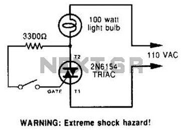
A triac can be utilized as a line-operated AC power switch that directly controls lamps, heaters, or motors. A brief current pulse into the gate activates the triac, and it remains on until the main current reverses. A triac, or...
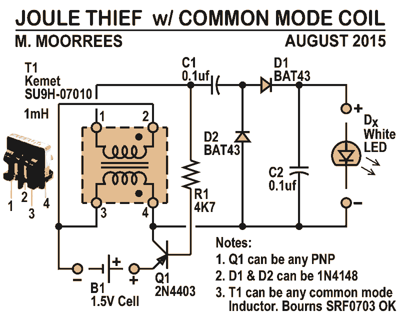
Like all joule thieves, this circuit boosts the voltage from a single 1.5V dry cell battery high enough to illuminate ultrabright GaN blue, green, or white LEDs. Instead of requiring a custom coil, it utilizes an off-the-shelf standard Kemet...
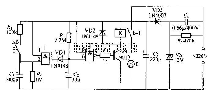
A 2-input NAND gate integrated circuit is used in the fabrication of a digital delay lamp circuit. This circuit is energized by a simple capacitive voltage rectifier, which operates by crossing the half line. The output terminal indicates the...