
Autofade Table Lamp Test Circuit

The autofade table lamp circuit is designed to provide a gradual dimming effect when the lamp is turned on or off, enhancing the ambiance of the environment. The core components typically include a microcontroller, a light-emitting diode (LED) or incandescent bulb, a power supply, and several passive components such as resistors and capacitors.
In this circuit, the microcontroller is programmed to control the brightness level of the lamp. It receives input from a user interface, such as a switch or a potentiometer, which allows the user to set the desired brightness level. The microcontroller then adjusts the output signal sent to the lamp, modulating the power supplied to it.
The omitted resistor R1, which is often included in similar circuits for current limiting or stability, may have been deemed unnecessary in this specific implementation. However, its inclusion in other designs can prevent excessive current flow, protecting the LED or bulb from damage.
The power supply provides the necessary voltage and current to the circuit, ensuring that all components operate effectively. Capacitors may be used to smooth out voltage fluctuations, while additional resistors can help in setting the correct operating conditions for the microcontroller and the lamp.
In summary, the autofade table lamp circuit utilizes a microcontroller to create a user-friendly dimming experience, with careful consideration given to component selection and circuit design to ensure reliability and performance.So, as you recall from my previous entry, I wanted to build an autofade table lamp based on this circuit diagram: This is how the test circuit looks in reality (the hand, by the way, is my nephew`s): (Note that resistor R1 in the schematic was omitted in the test circuit. Didn`t need it, turns.. 🔗 External reference
Related Circuits
Tro telephones can be utilized as an intercom through the implementation of this circuit. Traditional rotary phones, particularly those that are non-electronic, may be the most effective for this purpose. Additionally, this method can also power handsets alone. The circuit...
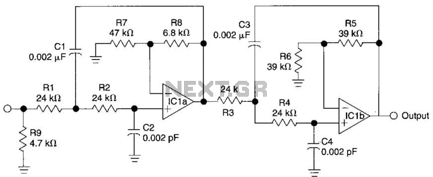
This circuit is a fourth-order low-pass filter designed for operation at kilohertz frequencies. The component values for resistors R1, R2, and capacitors C1, C2, as well as resistors R3, R4 and capacitors C3, C4 can be adjusted for functionality...
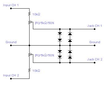
For simple electronic circuits, it may be sufficient to gain qualitative insights on dedicated electrical signals. This interface circuitry allows the line-in input of a standard PC sound card to be utilized as a 2-channel oscilloscope. Although this setup...
Figure 7-2 illustrates the FSK (Frequency Shift Keying) signal demodulation circuit, which is built using a digital phase-locked loop. This circuit features two oscillators operating at distinct frequencies: crystal oscillator X with a frequency of 983.04 kHz and crystal...
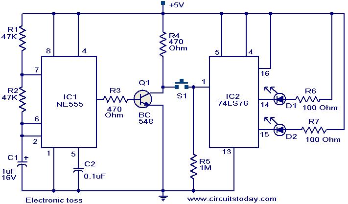
The circuit described can be utilized for tossing a coin, serving as a random generator for head or tail outcomes. This circuit is applicable in various games where a coin toss is required to initiate play. It employs two...
Free domains and hosting with up to 1GB of disk space, unlimited transfer, and access to PHP as well as 5 MySQL databases. The maximum size of a single file is not limited. This service offers a robust web hosting...