
Audio Fader

The circuit operates primarily through the interaction between the components Q1, Q2, R5, R6, and C3. Q1, functioning as the main amplification stage, relies on the emitter resistance to modulate its gain. The FET Q2 acts as a variable resistor, controlling the amount of current flowing through the emitter of Q1. This setup allows for dynamic adjustment of the amplifier's characteristics based on the position of switch SI.
When SI is switched to the up position, C3 begins to discharge through R5, which diminishes the voltage across the emitter of Q1. As a result, Q2 transitions toward a cut-off state, which reduces the overall gain of the amplifier. This behavior is crucial for applications requiring a gradual decrease in output signal, such as audio fading effects.
In contrast, when SI is toggled to the down position, the current through Q2 increases, enhancing the gain of Q1. The extent of this gain increase is influenced by the resistance value of R6, which can be adjusted to fine-tune the amplifier's response. Consequently, this flexibility allows for precise control over the amplification characteristics.
The combination of R5 and C3 plays a significant role in determining the fade rates. By varying the resistance of R5 or the capacitance of C3, users can create a range of fading effects, making the circuit versatile for different applications, such as in sound engineering, where gradual transitions in audio levels are often required. This circuit exemplifies a straightforward yet effective approach to gain control in amplification systems, highlighting the importance of component interaction in achieving desired performance outcomes. In this circuit, Ql is a simple amplifier that has its gain controlled by a variable emitter resistance supplied by FET Q2. In the up position of SI, C3 discharges through R5 and the gain of Ql decreases because Q2 is driven toward cut-off. In the down position, Q2 conducts more, depending on the setting of R6, which causes a gain increase.
By varying R5 or C3, various fade rates can be obtained.
Related Circuits
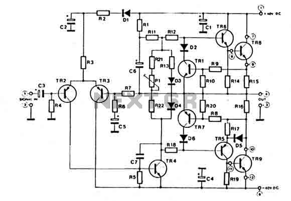
This amplifier features a high-quality circuit equipped with complete short circuit protection and exhibits very low total harmonic distortion (T.H.D.) across a full range of frequencies. It requires a symmetrical power supply of ±40V. The output power transistors are...
Operating radio transmitters without a license is illegal in most countries, so caution is advised with transmitter circuits. This FM low-power circuit is designed to operate within the 87-108 MHz band II, providing a range of approximately 20 to...
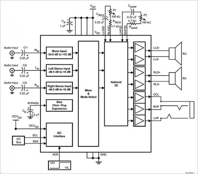
The LMC568 is an amplitude-linear phase-locked loop that includes a linear voltage-controlled oscillator (VCO), fully balanced phase detectors, and a carrier detect output. It utilizes LMCMOS technology to achieve high performance while maintaining low power consumption. The VCO features...
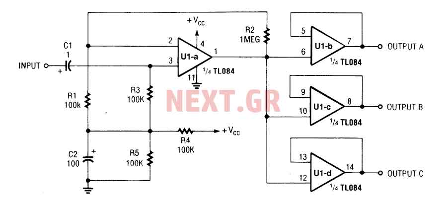
The three-channel amplifier output distribution uses a single TL084. The first step is to capacitive coupling with a 1.0 µF electrolytic capacitor. The entries are railways Vee Y2 or 4.5 V. This allows using a single 9 V power...
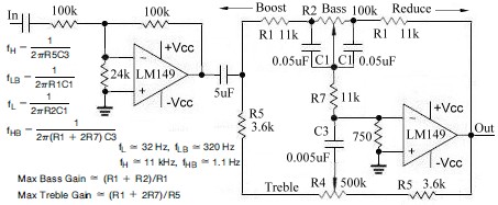
This topic continues from the more general Passive Tone Control circuit, which begins using only passive filters. This circuit follows the previous design, although the component values are different and in an alternate configuration. An audio tone control combines...
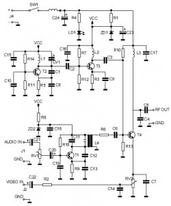
This is the circuit diagram of an audio/video modulator. The circuit converts audio and video signals into a UHF TV signal, allowing a video signal from a camera or other source to be connected to a standard TV set....