
Audio/Video to UHF TV Signal Converter (Modulator)
")
The audio/video modulator circuit serves as a crucial link between various video sources, such as cameras and TV sets, by converting the input signals into a compatible format for UHF transmission. This allows for seamless integration of video content into standard television systems, enhancing viewing experiences. The circuit is designed to ensure high fidelity in both audio and video output, utilizing components that are readily available and easy to assemble.
The video amplifier circuit, based on the LH0032 operational amplifier, is engineered for high-speed processing of video signals. The choice of resistors and capacitors is critical for maintaining signal integrity and minimizing distortion. Each component value is selected to optimize the performance of the amplifier, ensuring that the output signal retains the quality of the original input.
The FM transmitter circuit designed by Paul K. Sherby employs a simple yet effective configuration using four transistors, which allows for efficient modulation of audio signals. The specified resistor values help set the gain and frequency response of the transmitter, while the use of a trimpot enables fine-tuning of the output level. The inclusion of diodes and transistors ensures reliable operation and signal amplification.
The mini FM receiver circuit, centered around the TDA7012T IC, showcases a compact design that is well-suited for portable applications. The component selection, including various capacitors and resistors, is tailored to maximize the receiver's sensitivity and selectivity, allowing for clear reception of FM broadcasts.
The surround sound decoder circuit is designed for integration into home audio systems, enhancing the listening experience by providing multi-channel audio output. The diverse range of resistor and capacitor values allows for precise tuning of the audio signals, ensuring balanced sound reproduction across different channels.
The high-quality FM transmitter circuit exemplifies the principles of RF design, providing a robust solution for audio transmission over significant distances. The use of a 9V battery for power supply ensures portability, making it suitable for various applications. The design emphasizes the importance of component selection and circuit layout in achieving optimal performance, particularly in terms of transmission range and audio clarity.This is the circuit diagram of audio/video modulator. The circuit will convert an audio and video signal into a UHF TV signal. It`s desired to connect a video signal originating from a camera or other video source to a normal TV set. The audio and video signal is converted into a UHF TV signal so that the signal can be received through the TV ante
nna input. The circuit kit of this audio/video modulator available to buy at electronickits. com. You may buy the complete kit of this circuit (PCB board and the components) there. This is schematic diagram of a video amplifier circuit, built based very high speed opamp IC LH0032. Parts List: R1 = 15K ©+15K © R2-3-4 = 10K © R5, R6, R7, R8, R9 = 1K © R10 = 820 © R11 = 1M © R12 = 100 © trimmer R13, R14, R15 = 47 © R14 = 10K © C1 = 10uF 63V MKT C2, C3, C4 = 100nF/63V C3 = 4. 7pF. The following diagram is the schematic diagram of 4 transistors FM transmitter circuit designed by Paul K.
Sherby. Components List: R1, R2, R8 = 1K R3 = 100K R4 = 150K R5, R7 = 10K R6 = 220 ohm R9 = 10 ohm P1 = 5K trimpot D1 = 1N4002 Q1, Q2 = 2N3904 Q3, Q4 = 7001, NTE123AP C1. This is the circuit diagram of mini FM received that build based on single FM IC TDA7012T. Component Parts List: R1 = 8k ©2 R2 = 10k © R3 = 390 © C1, C3 = 10nF C2, C6, C9, C16 = 100nF C4 = 33pF C5 = 25pF trimmer (Murata type TZB4Z250AB10R00) C7, C10 = 1nF5 C8 = 820pF C11 = 1nF C12.
The following diagram is an small surround sound decoder schematics. You may use this decoder surround sound systems for your home audio system. Parts List: R1-2-7-8-12-13-18-19-20=47Kohm R3-4-5-6-21-22-34-35=10Kohm R9-10-11-14-15-16-17=15Kohm R=23-24-25-33-36=100ohm R26-27-28-31-32=100Kohm R29-30=5. 6Kohm C1-8=47uF 25V C2-7-9-14-23=47nF 100V C3-6=1uF 100V C4-5-10=33pF 100V C11-12-15=10uF 25V C13=82nF C16=18pF 100V C17=100pF mini adjustable capacitor C18=2.
2nF C19=4. 7uF 25V C20=100nF 100V C21=10nF C22=180pF. This the Good Quality FM transmitter for your stereo or any other amplifier gives you a pretty good signal strength up to a range of 500 metres having a power output of about 200 mW. This circuit can be operated with a 9V battery. The audio-frequency modulation stage is constructed close to transistor BF494 (T1), . This circuit is a powerful three stage, 9V FM transmitter (Tx) with a range of up to 1 kilometer in the open.
It uses an RF transistor in its output stage and two BC547`s for the first two stages. Distance of trans-mission is critically dependent on the operating Conditions (in a building or out on. 🔗 External reference
Related Circuits
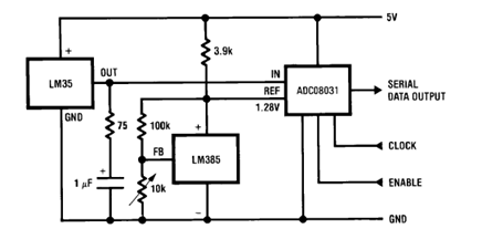
The circuit illustrates a Temperature to Digital Converter diagram utilizing the LM35 sensor, which includes a beneficial bypass capacitor connected from VIN to ground and a series RC damper. The described circuit employs the LM35 temperature sensor, a precision integrated...
Figure 7-2 illustrates the FSK (Frequency Shift Keying) signal demodulation circuit, which is built using a digital phase-locked loop. This circuit features two oscillators operating at distinct frequencies: crystal oscillator X with a frequency of 983.04 kHz and crystal...
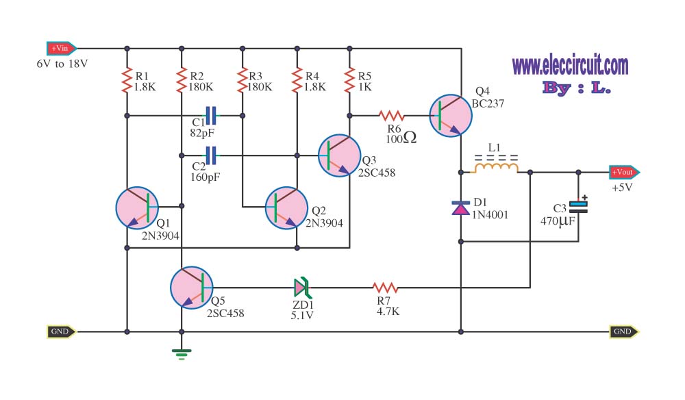
The circuit reduces voltage size or functions as a step-down voltage converter circuit, which is a DC regulated circuit model utilizing a switching converter. This design generates a specific voltage output. The step-down voltage converter, also known as a buck...
I realized the first schematic shown here, because it's more simple, but I took all information about the other pins from the second schematic. Be careful with all connections and control everything more than once to ensure the circuit...
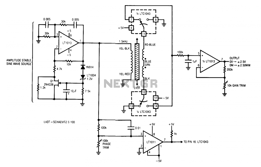
A1 and its associated components provide an amplitude-stable sine wave source. The positive feedback path utilizes a Wien bridge, tuned to 1.5 kHz. The LT1004 reference and additional components in A1's negative feedback loop stabilize the amplifier at unity...
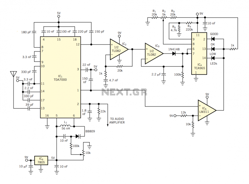
The IC has an FLL (frequency-locked-loop) structure. The filtered output of the FM discriminator frequency-modulates the local oscillator to provide negative-feedback modulation. The result is compression of the signal at the output of the mixer. Thus, the IF bandpass...