
Audio frequency generator

1. Signal source, to check if amplifier stages actually work (requires additional signal tracer);
2. Measurements of AC gain at various frequencies, i.e. assessment of frequency curve and -3 dB bandwidth (requires AF millivoltmeter);
3. Examination of the transient response of a circuit: do squarewaves cause ringing or oscillation? (requires an oscilloscope);
4. Assessment of the overload margin of an amplifier, i.e. determining the input voltage required for onset of clipping (visible check on a scope);
5. Distortion measurements (please note: low levels of distortion, i.e. < 0.1%, cannot be determined with the circuit described here)
The instrument consists of four different modules within a single enclosure, and is fed from an external (+ and - 15V) power supply. The modules are:
Sinewave generator with amplitude stabilization circuit [1];
Schmitt trigger (sine-to-squarewave converter) [2];
600 Ohm line driver (with stepped attenuator and volume control) [3];
Output indicator [4].
Most sinewave generators (including the circuit from publication 1) can be tuned continuously over a 1:10 range of frequencies, using a stereo potmeter (audio taper). Inspired by reference 4, I used a different approach. My generator is tuned in small steps (0.1 on a log scale) using a dual rotary switch with 12 positions. The resistors wired to the switch are accurate within 1%; proper values are obtained by wiring standard resistors in series. Much better tracking is obtained with a stepped attenuator than with a common stereo potmeter, resulting in lower distortion. Resistor values can be calculated with the formula: f = 1/(2*PI*R*C), in which PI = 3.14159 (R in Ohms and C in Farads). The capacitors which I employed were also selected for low tolerance (accurate values), using a digital capacitance meter. The combination of RC network and inverting amplifier causes a 90 degrees phase shift at a frequency determined by the RC time of the network. The two stages (A1 and A2) in series have 180 degrees phase shift at that particular frequency. Inverting amplifier A3 causes an additional 180 degrees phase shift and it provides sufficient gain to allow the system to oscillate at the selected frequency (a combined phase shift of 360 degrees corresponds to positive feedback). Capacitor C5 has been added in the feedback loop of A3 to suppress undesired parasitic RF oscillations above 100 kHz. The output voltage of A2 and A3 is rectified by the diodes D1 and D2 and fed to the inverting input of A4 via the variable resistor P3. The opamp A4 compares this rectified voltage with a reference voltage which is provided by the zener diode D4. The apparent drain-source resistance of FET T1 is dependent on the difference between output and reference, since the gate of T1 is driven by opamp A4. Thus, the input voltage of A3 is continuously adjusted and the output of the generator is maintained at a constant level. A number of precautions were taken to ensure proper operation of the amplitude stabilizing circuit. Capacitor C3 in the feedback loop integrates the input signal of A4; C4 and R12 have been added to suppress bouncing of the regulatory mechanism. Diode D3 was added to provide overload protection for the gate of T1. The article in Elektuur specified a BF256C for T1; I replaced this by a BF245C since I had that FET in my junkbox. Amplitude stabilization with a JFET normally results in a distortion of the sinewave of 1% or more, but the ingenious circuit of mr.Mieslinger causes distortion to remain below 0.1% over the audio range.
An audio frequency generator is an essential instrument for various applications in electronics. It serves as a reliable signal source for testing and troubleshooting amplifier stages, enabling engineers to verify functionality and performance. The generator's capability to produce sine and square waves across a wide frequency range makes it suitable for measuring AC gain, assessing frequency response, and determining the -3 dB bandwidth of audio circuits.
The design of the generator comprises four distinct modules, each playing a crucial role in the overall functionality. The sinewave generator employs an amplitude stabilization circuit that ensures consistent output levels despite variations in load or power supply fluctuations. The Schmitt trigger module converts the sine wave to a square wave, providing a sharp and clean signal that is essential for transient response testing. The 600 Ohm line driver module is equipped with a stepped attenuator and volume control, allowing for precise output level adjustments while minimizing distortion.
The tuning mechanism of the generator is designed for accuracy and reliability. The use of a dual rotary switch facilitates precise frequency selection in small increments, ensuring better tracking compared to conventional potentiometer-based systems. This design choice results in reduced distortion and improved signal integrity. The RC network combined with inverting amplifiers allows for effective phase manipulation, enabling the generator to oscillate at the desired frequency with minimal distortion.
The amplitude stabilization feature utilizes feedback from the output voltage to maintain a constant signal level. The integration of capacitors and resistors in the feedback loop enhances the stability of the circuit, while protective components safeguard against potential overload conditions. The choice of FETs and careful selection of passive components further contribute to the generator's performance, ensuring that distortion remains below 0.1% throughout the audio range.
Overall, the audio frequency generator is a sophisticated tool that not only meets the needs of audio testing but also provides valuable insights into circuit behavior, making it an indispensable asset for engineers and technicians in the field of electronics.My generator can produce sine- and squarewaves with frequencies between 1 Hz and 100 kHz and amplitudes ranging from zero to 1.55 Veff in 600 Ohms. Sinewave distortion is 0.1% or less between 20 Hz and 20 kHz, somewhat greater outside this region. The output voltage varies less than 0.1 dB within the audio range (20 Hz to 20 kHz); there is some rolloff (less than 1 dB) at the frequency extremes.
An audio frequency generator is a very useful addition to the workbench. Common purposes of this instrument are: 1. Signal source, to check if amplifier stages actually work (requires additional signal tracer); 2. Measurements of AC gain at various frequencies, i.e. assessment of frequency curve and -3 dB bandwidth (requires AF millivoltmeter); 3. Examination of the transient response of a circuit: do squarewaves cause ringing or oscillation? (requires an oscilloscope); 4. Assessment of the overload margin of an amplifier, i.e. determining the input voltage required for onset of clipping (visible check on a scope); 5. Distortion measurements (please note: low levels of distortion, i.e. < 0.1%, cannot be determined with the circuit described here) The instrument consists of four different modules within a single enclosure, and is fed from an external (+ and - 15V) power supply. The modules are: Sinewave generator with amplitude stabilization circuit [1]; Schmitt trigger (sine-to-squarewave converter) [2]; 600 Ohm line driver (with stepped attenuator and volume control) [3]; Output indicator [4].
Most sinewave generators (including the circuit from publication 1) can be tuned continuously over a 1:10 range of frequencies, using a stereo potmeter (audio taper). Inspired by reference 4, I used a different approach. My generator is tuned in small steps (0.1 on a log scale) using a dual rotary switch with 12 positions.
The resistors wired to the switch are accurate within 1%; proper values are obtained by wiring standard resistors in series. Much better tracking is obtained with a stepped attenuator than with a common stereo potmeter, resulting in lower distortion.
Resistor values can be calculated with the formula: f = 1/(2*PI*R*C), in which PI = 3.14159 (R in Ohms and C in Farads). The capacitors which I employed were also selected for low tolerance (accurate values), using a digital capacitance meter.
The combination of RC network and inverting amplifier causes a 90 degrees phase shift at a frequency determined by the RC time of the network. The two stages (A1 and A2) in series have 180 degrees phase shift at that particular frequency. Inverting amplifier A3 causes an additional 180 degrees phase shift and it provides sufficient gain to allow the system to oscillate at the selected frequency (a combined phase shift of 360 degrees corresponds to positive feedback).
Capacitor C5 has been added in the feedback loop of A3 to suppress undesired parasitic RF oscillations above 100 kHz. The output voltage of A2 and A3 is rectified by the diodes D1 and D2 and fed to the inverting input of A4 via the variable resistor P3.
The opamp A4 compares this rectified voltage with a reference voltage which is provided by the zener diode D4. The apparent drain-source resistance of FET T1 is dependent on the difference between output and reference, since the gate of T1 is driven by opamp A4.
Thus, the input voltage of A3 is continuously adjusted and the output of the generator is maintained at a constant level. A number of precautions were taken to ensure proper operation of the amplitude stabilizing circuit. Capacitor C3 in the feedback loop integrates the input signal of A4; C4 and R12 have been added to suppress bouncing of the regulatory mechanism.
Diode D3 was added to provide overload protection for the gate of T1. The article in Elektuur specified a BF256C for T1; I replaced this by a BF245C since I had that FET in my junkbox. Amplitude stabilization with a JFET normally results in a distortion of the sinewave of 1% or more, but the ingenious circuit of mr.Mieslinger causes distortion to remain below 0.1% over the audio range.
🔗 External reference
Related Circuits

This is a stereo audio amplifier designed for automotive applications. The circuit utilizes a single integrated circuit, the TDA1553, along with several external components. This IC is responsible for managing the stereo audio system in a vehicle. The TDA1553CQ...
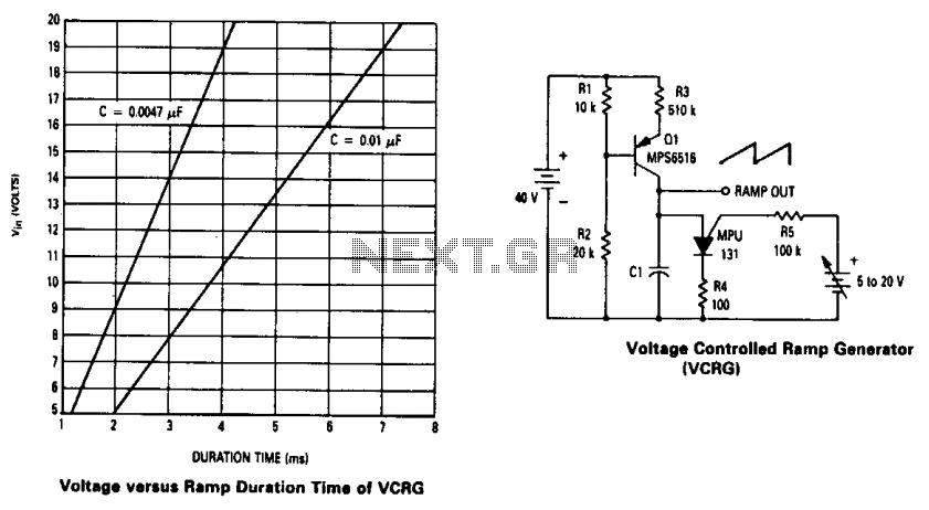
The current source created by Q1 in combination with capacitor C1 determines the duration of the ramp. As the positive DC voltage at the gate varies, the peak point firing voltage of the Programmable Unidirectional Thyristor (PUT) is altered,...
The circuit was designed to create an electronic oscillator known as a Wien Bridge Oscillator, which can be used for the creation of low-frequency sine waves. The Wien Bridge Oscillator is a type of electronic oscillator that generates sine waves....
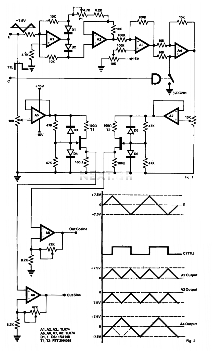
The presented circuit generates waveforms from any function generator that produces a triangular output and a synchronized TTL square wave. Amplifiers A1 and A2 function as a two-phase current rectifier by inverting the negative voltage at the input of...
For all the subsequent tests, a high-quality signal generator from BlackStar was utilized. The PicoScope trace displayed below illustrates a pure 1 kHz tone from the signal generator. It is important to note that while the screenshots below depict...
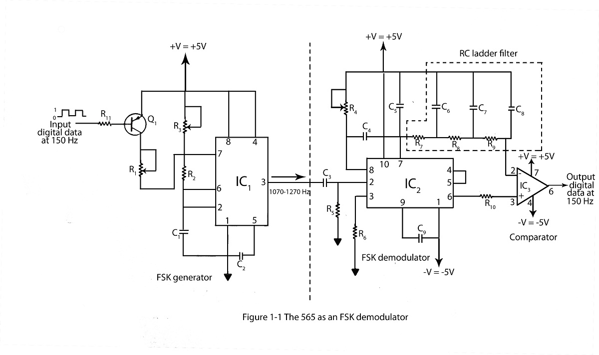
The frequency shifting keying technique is utilized to transmit binary data. The circuit diagram includes a description of an FSK demodulator that employs the 565 integrated circuit for frequency shift keying. The frequency shift keying (FSK) technique is a form...