
Programmable Unijunction Transistor (PUT) Flasher Circuit
 Flasher")
The circuit utilizes a programmable unijunction transistor (PUT) to demonstrate its operation as an oscillator. The PUT, which is a three-terminal device, is capable of generating a pulse output when a specific threshold voltage is exceeded. This characteristic makes it suitable for applications such as timing circuits and flashers.
In the schematic, the PUT is connected in a basic flasher configuration. The circuit typically includes a resistor-capacitor (RC) network that determines the oscillation frequency. The capacitor charges through the resistor until the voltage across it reaches the gate trigger voltage of the PUT. At this point, the PUT turns on, allowing current to flow through the load (often an LED or a small bulb) and discharging the capacitor. Once the capacitor discharges below a certain threshold, the PUT turns off, and the cycle repeats.
Key components in the circuit include the PUT, a resistor (R) for current limiting, a capacitor (C) for timing, and a load (such as an LED). The values of R and C can be adjusted to modify the flashing rate of the output. The circuit can be easily assembled on a proto-board, allowing for rapid prototyping and experimentation.
Proper attention should be given to the power supply voltage and the ratings of the components to ensure reliable operation. The circuit can serve as an educational tool for understanding the behavior of programmable unijunction transistors in oscillating applications.This is simple circuit that illustrates the function of the programmable unijunction transistor. It may be quickly wired on a proto-board. PUT Flasher Spec.. 🔗 External reference
Related Circuits
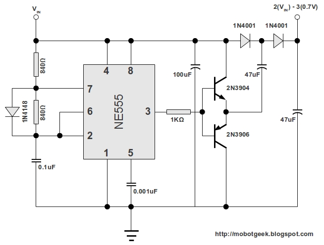
This DC voltage doubler circuit generates a voltage that is double its supply voltage. It is advantageous when a higher voltage level is required from a single lower voltage power supply. Due to the low current consumption in such...
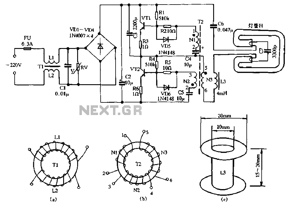
The circuit diagram illustrates a dedicated electronic ballast circuit for a 16W2D single-ended energy-saving lamp. The RFI filter circuit consists of components such as zinc oxide varistors for protection, bridge rectifiers, a high-frequency oscillator, and an LC series output...
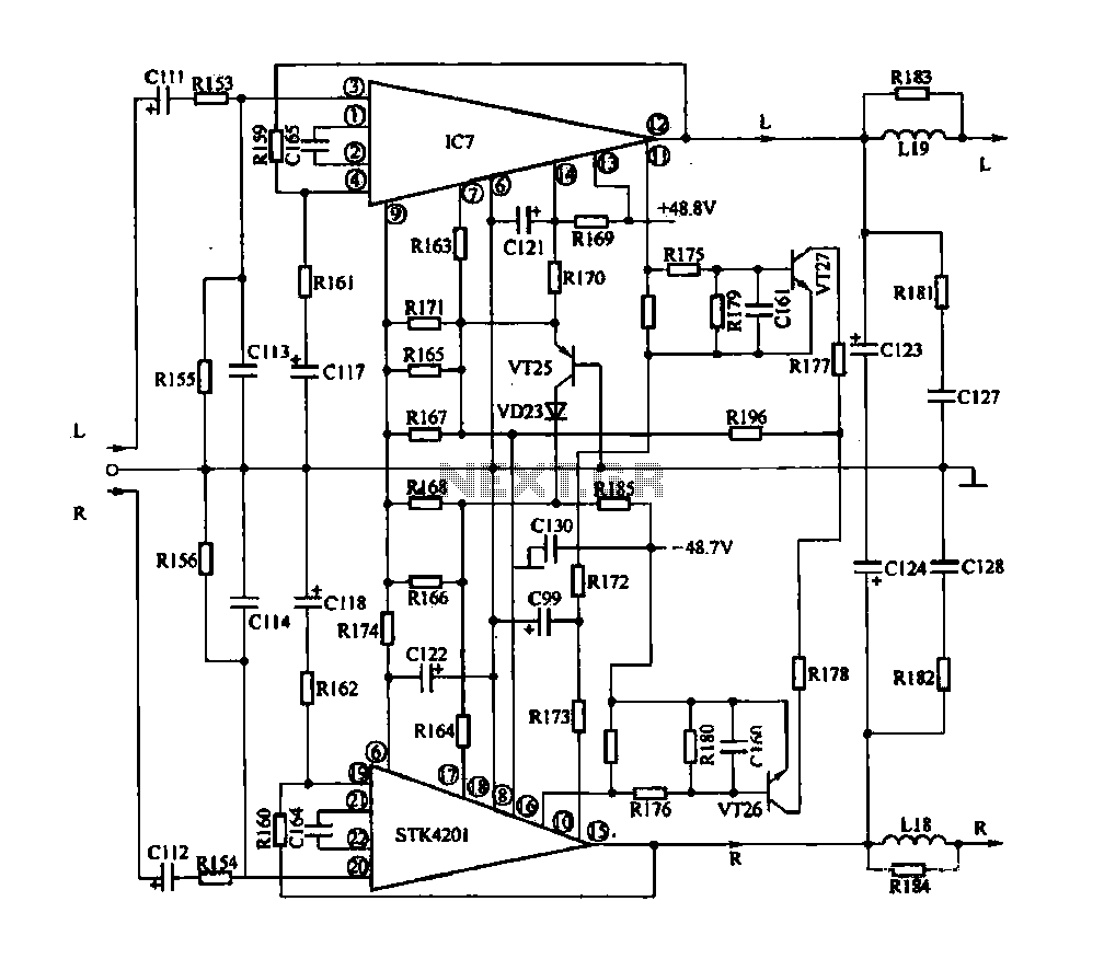
The rapid advancement of integrated circuit technology has led to the widespread emergence of integrated circuit amplifiers. These amplifiers exhibit high levels of technology and performance indicators. Their advantages include compact size, simplified circuitry, exceptional performance, and comprehensive protection...
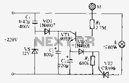
Utilize the call sheet to touch the electrical threshold M, which causes the E lamp to light up. When the same interval subparagraph is triggered, the lights will automatically turn off. A voltage regulator rectifier circuit is formed using...
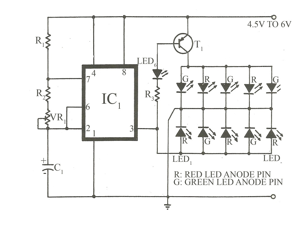
This circuit is similar to various published flasher circuits that utilize the IC 555 as a free-running multivibrator. The primary distinction is in the method of flashing bi-color LEDs. When the output at pin 3 of the IC 555...
The induction coil detects the magnetic field flux during phone calls, amplifies the signal, and triggers the LED. These circuits are designed for the phone to rest on the pickup coil. The electromotive force (emf) from the bell electromagnets...