
Voice Activated Switch And Amplifier Circuit

The circuit in question is versatile and can be employed in various communication and control scenarios, including but not limited to audio transmission and remote control systems. The inclusion of audio output allows for the transmission of sound signals, making it suitable for applications such as intercom systems or wireless audio devices. The DC control outputs enable the circuit to interface with other electronic components, facilitating the control of devices or systems based on the received signals.
Resistor R9 plays a critical role in defining the control threshold for the circuit. By adjusting the resistance value of R9, the sensitivity of the circuit can be fine-tuned, allowing it to respond accurately to the desired input signals. This control threshold is essential for ensuring that the circuit activates or deactivates at the appropriate signal levels, thereby enhancing its reliability and performance in various operational environments.
Additional components may also be included in the circuit design to enhance functionality. For instance, capacitors could be used to filter noise from the audio output, ensuring a clear sound signal. Diodes might be incorporated for protection against voltage spikes, safeguarding sensitive components within the circuit. Furthermore, operational amplifiers could be utilized to amplify weak signals, improving the overall signal quality and performance of the circuit.
In summary, the circuit is designed for effective communication and control in various applications, providing both audio and DC outputs. The adjustable control threshold via R9 allows for customization based on specific operational requirements, making it a valuable component in modern electronic systems. In certain applications, such as transmitter or other communications and control applications, this circuit should be useful. Both audio output and dc control outputs are provided. R9 sets the control threshold.
Related Circuits
This circuit diagram represents an ECM Mic Preamplifier. It is a microphone amplifier compatible with Electret Condenser Microphones (ECM). The preamplifier exhibits an excellent dynamic range, capable of handling audio levels from a whisper to a scream; however, caution...
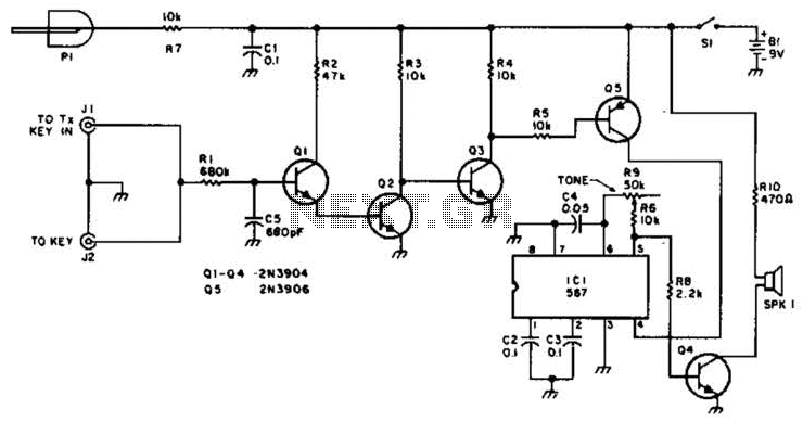
For use with low-power transmitters that require a positive keying voltage. The transistors Q1, Q2, and Q3 are configured as a switching amplifier. When the key is pressed, the collector of Q3 is pulled to ground, which activates Q5...
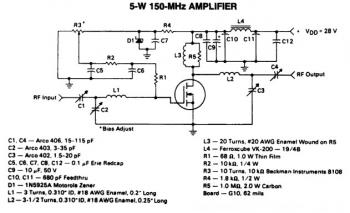
This is a 5W -150MHz RF amplifier circuit that utilizes the MRF123 TMOSFET. The MRF123 is a high-gain FET which may exhibit instability at both VHF and UHF frequencies; therefore, a 68 Ohm input loading resistor is employed to...

The interface circuit is placed between the computer's standard video signal output terminal and the television. It amplifies the standard 1V (Peak-to-Peak) video signal to 3V (Peak-to-Peak). The negative feedback circuit consists of transistors T1 and T2, providing a...
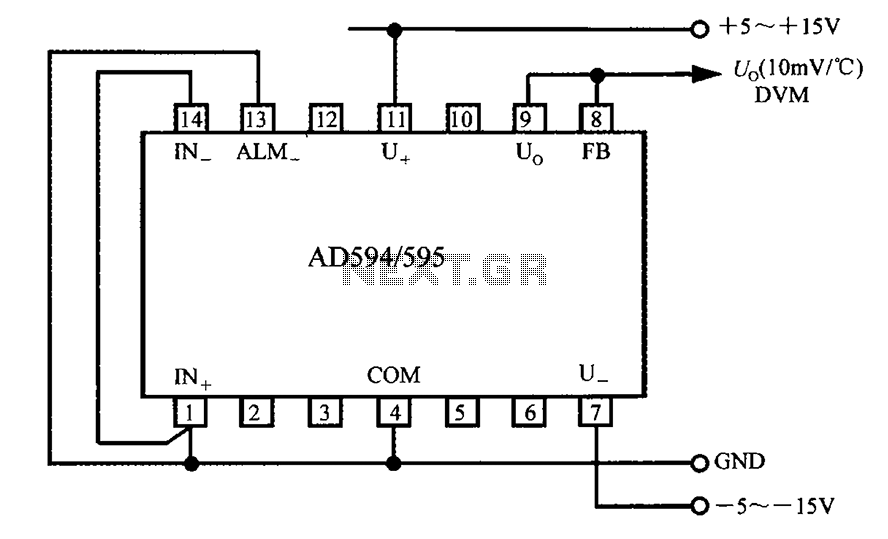
The AD594/595 can be configured to measure temperature in Celsius. In the circuit diagram, the IN+ and IN- terminals should be shorted to the COM terminal. The output voltage (Uo) has a temperature coefficient of 10 mV/°C, which can...
This circuit is a simple analog multiplier. The operation of the circuit can be understood by considering A2 as a controlled gain amplifier. It involves components such as an analog multiplier, a log-antilog circuit, and a summing junction, along...