
Audio frequency meter

The described meter operates on the principle of time averaging, which is a method used in electronic measurement systems to convert varying input signals into a stable output. In this case, the meter takes an alternating current (AC) signal, which fluctuates in frequency, and processes it to produce a direct current (DC) output that accurately reflects the frequency of the input.
To achieve this, the meter typically employs a combination of signal conditioning components, including filters, amplifiers, and rectifiers. The input signal is first filtered to remove any high-frequency noise that may interfere with accurate frequency measurement. This is often done using low-pass filters that allow only the desired frequency range to pass through.
Next, the filtered signal is amplified to ensure that it reaches a suitable level for further processing. The amplification stage is crucial as it enhances the signal strength, making it easier to analyze and convert. After amplification, the signal undergoes rectification, which converts the AC signal into a DC signal. This is usually accomplished using a precision rectifier circuit, which provides a more accurate representation of the input frequency.
The time averaging mechanism then takes place, where the rectified signal is averaged over a specific time interval. This averaging process smooths out rapid fluctuations in the signal, resulting in a stable DC output that is directly proportional to the frequency of the input signal. The output can then be displayed on a meter or used for further processing in a control system.
Overall, this meter design is essential for applications where precise frequency measurement is required, such as in telecommunications, audio signal processing, and various industrial automation systems. The ability to convert frequency to a proportional DC signal allows for easier integration with digital systems and provides a clear representation of the input signal's characteristics.The meter uses time averaging to produce a direct current that is proportional to the frequency of the input signal.
Related Circuits
The LM3915 is a monolithic integrated circuit that senses analog voltage levels and drives ten LEDs providing a logarithmic 3 dB/step analog display. LED current drive is regulated and programmable, eliminating the need for current limiting resistors. The IC...
Digital speedometers are typically found in luxury vehicles and high-performance motorcycles. However, in the event of a malfunction in a mechanical speedometer, an alternative solution is necessary. This digital speedometer displays speed and distance in kilometers for both motorcycles...
The output of this circuit should be connected to a high-impedance load, typically greater than 100K ohms, while noting that the impedance of capacitor C4 is approximately 3K ohms. A PNP transistor may also be utilized, requiring adjustments to...
This may appear to be a basic inquiry, but the individual is a beginner in electronics. A preamplifier has been constructed to amplify the signal from a small speaker that is utilized. The preamplifier circuit is designed to increase the...
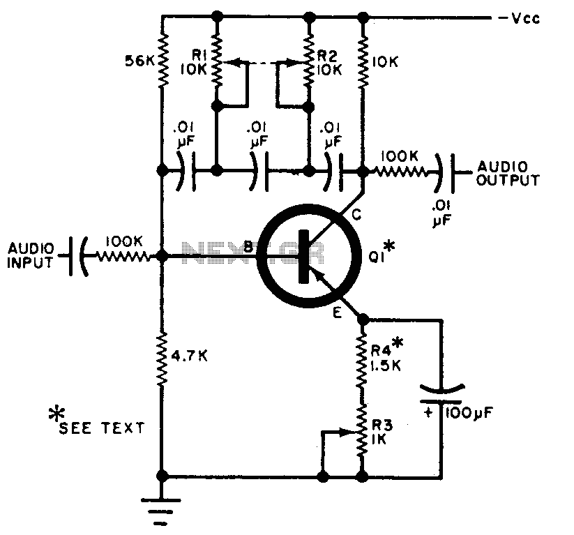
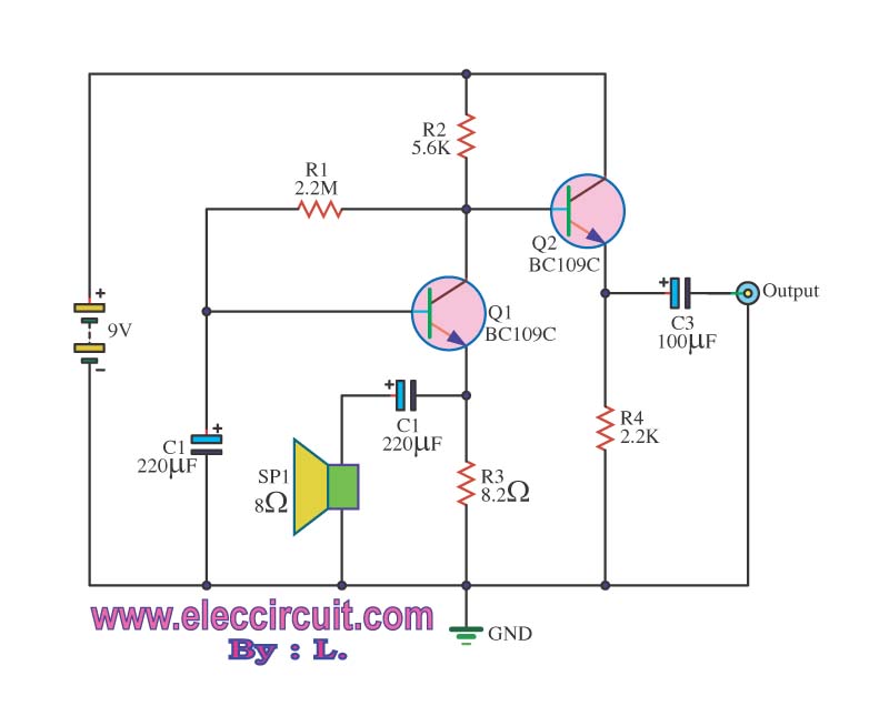
The circuit can be selectively tuned to two closely related tones. The selective frequency is determined by the values of the feedback circuit connected to the collector and base of Q1, which includes capacitors and resistors. When the specified...
The LM35 from National Semiconductor is a precision centigrade temperature sensor that provides an analog output voltage. It operates within a temperature range of -55°C to +150°C and has an accuracy of ±0.5°C. The output voltage corresponds to 10mV...