
Split Power Supply Circuit for Power Amplifier

The 150W power amplifier circuit is designed for straightforward assembly, making it accessible for hobbyists and engineers alike. The use of Darlington transistors enhances the current gain, allowing for efficient power handling and amplification. The significance of proper thermal management through the installation of a heatsink cannot be overstated, as excessive heat can lead to thermal runaway and eventual failure of the transistors.
The TDA2040 IC operates efficiently in audio applications, providing a reliable solution for achieving high fidelity sound output. The bridge configuration effectively doubles the output power, making it suitable for driving larger speakers or subwoofers. The circuit's reliance on a split power supply enhances its performance, ensuring that the amplifier operates within optimal voltage levels.
The TDA2050 amplifier circuit further exemplifies the potential for high-quality audio reproduction in compact designs. Its capability to deliver 32W output with minimal distortion makes it a preferred choice for budget audio systems, allowing users to enjoy enhanced sound quality without significant investment.
The "safari" amplifier circuit, with its robust design utilizing well-regarded power transistors, represents a powerful option for audio amplification needs. The inclusion of a substantial heatsink is vital for maintaining performance and reliability under high load conditions.
In contrast, the 1500W power amplifier circuit by Rod Elliott showcases an advanced design capable of delivering exceptional audio output for professional applications. The extensive use of power transistors ensures that the circuit can handle high power demands, necessitating careful consideration of the power supply specifications to match the amplifier's capabilities.
Overall, these amplifier circuits illustrate a range of options for various audio amplification needs, from simple home audio systems to professional-grade setups, emphasizing the importance of circuit design, component selection, and thermal management in achieving desired performance outcomes.This is the very simple circuit diagram of 150W power amplifier. The circuit is easy enough to built without PCB. The power output range is about 100-150W depends to the power supply and the Darlington`s you use for the amplifier. Heatsink is a must since the final transistor is going to hot when the amplifier. This is a Hi-Fi power amplifier cir cuit build based on single power amplifier IC TDA2040. The single TDA2040 has able to deliver 20W power output. The bridge amplifier which consist of double TDA2040 can deliver 30W power output (8 ohm loudspeaker). About power amplifier IC TDA2040: The TDA2040 is a monolithic integrated circuit in Pentawatt. If you want to create an amplifier that is able to produce a good sound output with low distortion audio, then this amplifier could be the right option for you.
This circuit using power supply split type with a maximum input voltage of 25V. Heatsink should be installed on the power IC to avoid excessive. Here is a Hi-Fi power amplifier circuit, built with a power IC TDA2050. This circuit will produce a power output up to 32watt. With good sound quality, high power and very low distortion feature, this circuit will be very suitable for simple and cheap audio systems. TDA2050 Amplifier Schematic diagram: TDA2050 Amplifier PCB Design: About. This 400W power amplifier circuit often called as "safari" amplifier. The 400W power amplifier built using two couples of power transistors that are TIP31 with TIP32 and 2N3055 with MJ2955.
These transistors are well known and widely used for the amplifier circuit and power supply circuit. Take a note that you must use aluminium heatsink. This is a very high 1500W power amplifier circuit diagram by Rod Elliott. The circuit is built using 10 pairs of power transistor MJ15024 and MJ15025 (or MJ21193/MJ21194), then it will use 20 pieces of power transistor for final amplification. With very high power audio output, then of course it will need power supply with. 🔗 External reference
Related Circuits
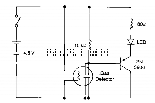
The circuit illustrates a basic yes/no gas detector. It utilizes three 1.5-V D cells as the power source, with SI functioning as an on/off switch. The heater is powered directly from the battery, while the electrodes are connected in...
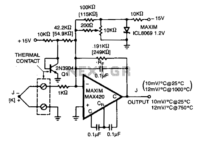
The MAX420 is operated at a gain of 191 to convert the 52 µV/°C output of the type J thermocouple to a 10 mV/°C signal. The -2.2 mV/°C temperature coefficient of the 2N3904 is added into the summing junction...
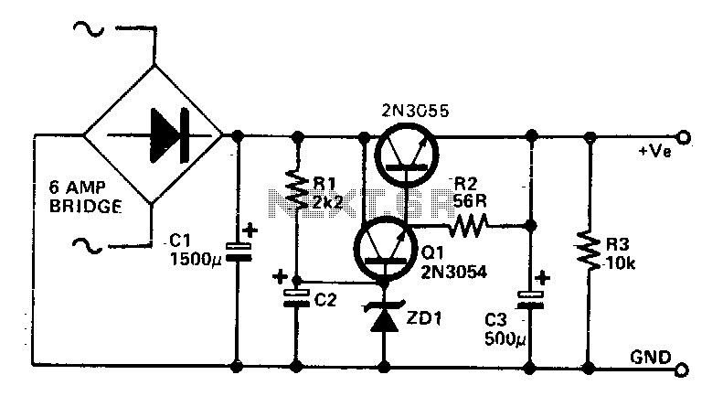
This circuit can be utilized in applications requiring high current with low ripple voltage, such as in high-powered Class AB amplifiers where high-quality audio reproduction is essential. Q1, Q2, and R2 can be considered as a power Darlington transistor...
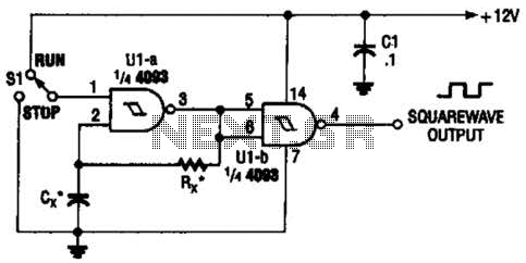
Two gates of the Quad 4093 are utilized to create an oscillator. The resistor (R) can range from approximately 5 kΩ to around 10 kΩ. The capacitor (Cx) can vary from about 10 pF to higher values, with the...
The ATMEL AVR programmer operates with the Windows program "Ponyprog," which is compatible with Windows 95, 98, and XP. The ATMEL AVR programmer is a device designed for programming AVR microcontrollers. It interfaces with the microcontroller through the ISP (In-System...
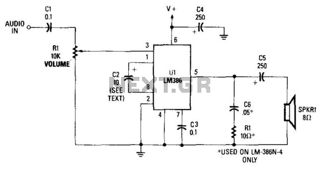
This simple receiver AF amplifier can supply several hundred milliwatts to an 8-ohm speaker. The gain is approximately 200X. If high gain is not required, C2 can be removed, resulting in a gain of 20. R1 and C6 are...