
audio graphic equalizer circuit

The audio graphic equalizer circuit operates by dividing the audio frequency spectrum into multiple bands, each of which can be independently adjusted to enhance or attenuate specific frequencies. The use of gyrators in this design allows for the simulation of inductive behavior without the need for physical inductors, thus contributing to a more compact and cost-effective circuit.
Each gyrator stage is configured to respond to a specific frequency range, with the faders providing user control over the gain for each band. The operational amplifier plays a critical role in ensuring that the input audio signal is amplified sufficiently to drive the gyrators, which in turn manipulate the signal's frequency response.
The center frequency (f) for each band can be calculated using the provided formula, which takes into account the values of the capacitors and resistors in the circuit. The quality factor (Q) is essential for defining the bandwidth of each filter, with higher Q values resulting in narrower passbands. The relationship between Q and the capacitor ratio is crucial for achieving the desired frequency response characteristics.
The impedance calculation is vital for understanding how the circuit interacts with other components in the audio system. The resistive component ensures stability, while the capacitive and inductive terms allow for the tuning of frequency response. This comprehensive approach to circuit design enables the creation of effective audio graphic equalizers capable of delivering high-quality sound tailored to user preferences.This is a design circuit for audio graphic equalizers, that are very common as commercial products but circuits for them are very rarely published. This circuit is a simple design circuit. The circuit is needs an op-amp for amplifying the input signal. This is the figure of the circuit. Only one gyrator stage is shown: all 7 gyrators are the same circuit, only the capacitors change, as shown in the chart. I have shown three of the seven faders to show where they go. A gyrator is a circuit using active devices and transistors to simulate an inductor. In this case the gyrator is the transistor acting with R1, R3 and C2. It could just as easily be a unity gain op-amp. The circuit includes three formulae: one which gives f, the the centre frequency of the band. The second shows how the Q is related to the capacitor ratio. The third shows the impedance presented by the circuit. Note that this includes 3 terms, the first purely resistive, the second is the capacitive contribution from C1 and the third is an inductive term from the gyrator. 🔗 External reference
Related Circuits
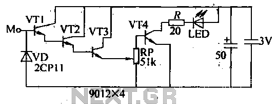
The image depicts a proximity switch circuit that includes the HMC1001 Hall effect sensor, an operational amplifier (AMP04), and a light-emitting diode (LED). In this configuration, the operational amplifier functions as a comparator. When a magnet with a length...
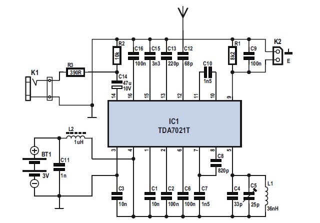
The TDA7021T FM radio receiver is designed for portable radios, supporting both stereo and mono output. It is particularly suitable for applications requiring low-voltage microcontroller interfacing. The integrated circuit features a built-in frequency locking loop (FLL) with a nominal...
The internal disconnection circuit for a blanket operates on the principle of induction. It includes a wire approximately 2 cm in length that senses the proximity of a charged mains power source. When the sensing wire is close to...
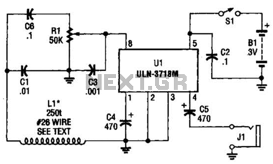
The VLF whistler receiver is designed to detect natural radio noise and signals that occur below 20 kHz. LI is a large loop antenna consisting of 250 to 300 turns of #26 gauge wire wound on a form with...
This circuit below shows a teleremote circuit that enables the switching on and off of appliances through telephone lines. It can be used. The teleremote circuit operates by utilizing telephone lines to control electrical appliances remotely. The primary components of...
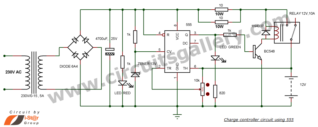
This is a simple DIY charge controller schematic created in response to a request from one of the readers on our Facebook page. The primary component of this automatic battery charger circuit is a 555 timer, which compares the...