
3170 IC For Telephone Remote Control Circuit

The teleremote circuit operates by utilizing telephone lines to control electrical appliances remotely. The primary components of this circuit typically include a telephone line interface, a microcontroller or relay module, and the connected appliances.
When a user makes a call to the designated telephone number associated with the teleremote system, the circuit detects the incoming call. The microcontroller processes the call signals and interprets the commands based on the duration of the ring or specific tones sent by the caller. For instance, a short ring may signify a command to turn an appliance on, while a longer ring could indicate a command to turn it off.
The circuit may also incorporate a relay or solid-state switch to handle the high current required by electrical appliances. This ensures safe operation, as the microcontroller typically operates at low voltage levels. The relay acts as an intermediary, allowing the low-power control signal from the microcontroller to switch the higher power required by the appliance.
Additionally, the teleremote circuit can be enhanced with features such as feedback indicators, which inform the user of the current state of the appliance (on or off) through LED indicators or through a voice response system. This feedback can be crucial for users to confirm that their commands have been executed successfully.
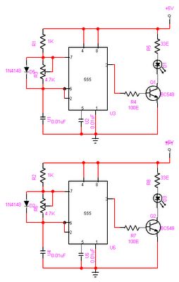
Overall, this teleremote circuit design provides a convenient solution for remotely managing household appliances, leveraging existing telephone infrastructure for control and communication.This circuit bellow shows a teleremote circuit which enables switching ?on? and ?off? of appliances through telephone lines. Can be used . 🔗 External reference
Related Circuits
The objective of this project is to create a controller-based model that counts the number of individuals entering a specific room and activates the lighting accordingly. This is achieved through the use of sensors that detect the current number...
The remote control robot circuit is illustrated in the accompanying figure. Figure 2-36(a) presents the circuit diagram, while figure 2-36(b) depicts the operating timing diagram. The robot's rotation process involves an ultrasonic launching circuit, which consists of a 40...
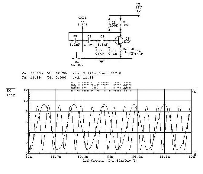
This project was a surprise as the BC547 transistor (equivalent to 2N2222) can be used to construct a 500mW linear amplifier that operates across the entire HF band with excellent spectral purity and without the need for neutralization. The...
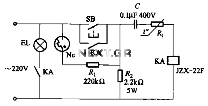
The circuit illustrated in Figure 2-49 is straightforward, featuring a cold Positive Temperature Coefficient (PTC) thermistor element. It utilizes the thermal resistance characteristics of the lamp to manage the delay time, which typically ranges from 10 to 30 seconds....
The Olimex P-40 development board will be utilized, though the circuit can also be constructed on a breadboard due to its simplicity. The schematic for the initial implementation of servo control is provided below. Servos, like any motors, can...
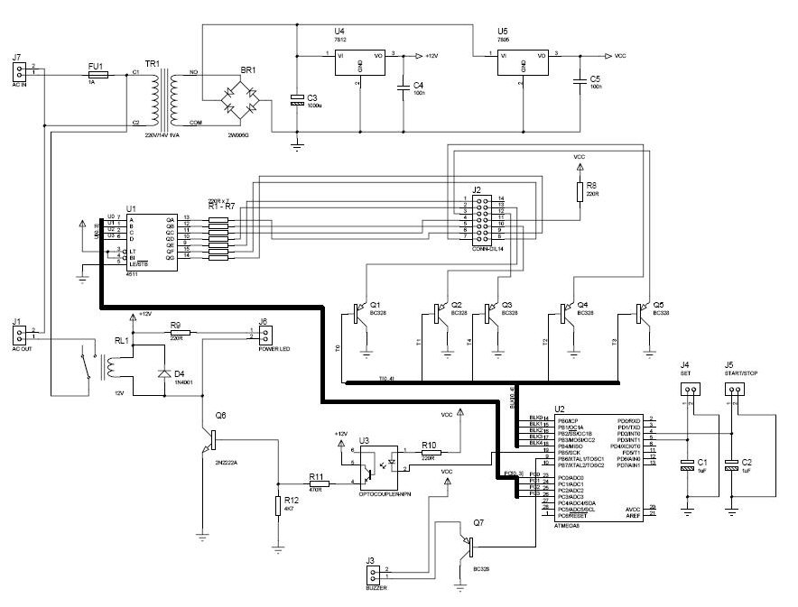
The procedure outlines the construction of a Box, Lamp System, and Countdown System utilizing the AVR Mega8 microcontroller. The system features four blacklight lamps, each rated at 15W, which emit radiation primarily in the UVA spectrum, peaking around 350nm,...