
audio mixer

The mixer circuit typically combines two or more input signals into a single output signal, often used in audio and radio frequency applications. The circuit may incorporate operational amplifiers, resistors, capacitors, and possibly diodes or transistors, depending on the desired functionality and complexity.
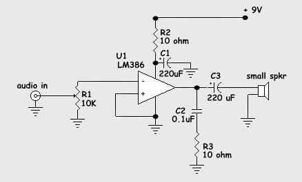
In the provided schematic, R1 and R2 serve as input resistors, which help to set the gain of the operational amplifier. The values of these resistors should be chosen based on the desired output level and impedance matching requirements. The operational amplifier will mix the input signals, and the output can be further processed or amplified as needed.
To ensure proper operation, it is crucial to verify the power supply connections and the configuration of the operational amplifier, including feedback components that stabilize the circuit and prevent distortion. Additionally, the layout of the circuit should minimize interference and maintain signal integrity, which is especially important in high-frequency applications.
Testing the circuit with known input signals can help determine its performance. If the output signal meets the expected criteria, the circuit can be deemed functional. If not, adjustments to resistor values or the operational amplifier configuration may be necessary to achieve the desired results.Hello. im going to make this mixer circuit.Im not sure if it work fine or not.Can you please check it for me ? Thank! In this schematic, i use R1=R2.. 🔗 External reference
Related Circuits
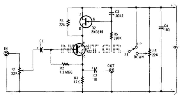
In this circuit, Q1 serves as a simple amplifier with gain control provided by a variable emitter resistance supplied by FET Q2. When switch SI is in the up position, capacitor C3 discharges through resistor R5, resulting in a...
Nice small audio amplifier which use only few parts to give good quality sound. This amp can be used as a simple booster, the heart of a more complicated amplifier or used as a guitar amp. Although not perfect,...

A very high-power amplifier with 10 pairs of power transistors. It can utilize MJ15024 and MJ15025 or MJ21193 and MJ21194. These 20 transistors function as the final active components. The design is based on four integrated circuits: TL072, TL074,...
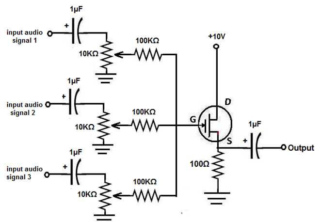
This project involves the construction of an audio mixer, a device designed to combine multiple audio signals into a single output. For instance, one input may consist of a solo vocal performance, while another could be background music. An...
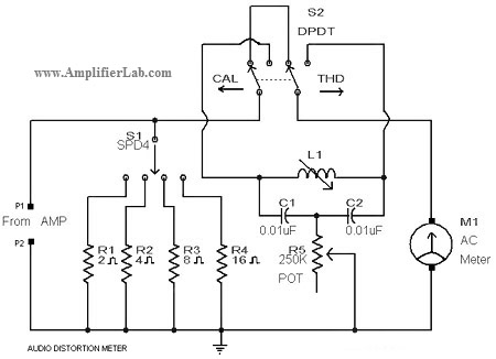
A circuit diagram of an audio distortion meter is presented here. An audio distortion meter is utilized to measure Total Harmonic Distortion (THD). The audio distortion meter is an essential tool in audio engineering, designed to quantify the level of...
The schematic diagram presented is of a twin "T" phase shift oscillator, an audio oscillator. This oscillator derives its name from the phase shift network formed by resistors R3, R4, and capacitors C1, C2, and C3. This network shifts...