
audio mixer in ads

This audio mixing circuit integrates two distinct signal sources: a triangular wave generator and a noise generator. The triangular wave generator produces a continuous waveform characterized by its linear rise and fall, making it suitable for various audio applications. The noise generator, on the other hand, creates random signals that can add texture and complexity to the audio output.
The circuit begins with the output from the triangular wave generator, which is connected to one of the input channels of the audio mixer. The noise generator's output is routed to another input channel of the same mixer. The audio mixer is designed to combine these two signals, allowing for independent adjustment of their levels through potentiometers. This feature enables the user to balance the contributions of the triangular wave and noise to achieve the desired sound texture.
The mixer employs operational amplifiers (op-amps) to facilitate the mixing process. These op-amps are configured in a summing amplifier configuration, which allows for the linear combination of the input signals. The output of the mixer then produces a composite waveform that represents the desired audio output.
To ensure optimal performance, filtering may be applied to the output signal to remove any unwanted frequencies and enhance the overall sound quality. This can be achieved using passive or active filter circuits, depending on the specific application requirements.
The final output can be connected to speakers or further processing equipment, allowing for versatile applications in audio engineering and sound design. Overall, this circuit serves as a foundational component in audio mixing, enabling creative manipulation of sound through the integration of various waveforms.The circuit used was basically for audio mixing, it had an input from the triangular wave generator and the noise generator. And it is passsed through the audio mixer to form the wave. 🔗 External reference
Related Circuits

With AudioWave 2.0 your soundcard becomes a comfortable LF-signal-generator, which produces signals from 1Hz to 20 kHz with a resolution of 1 Hz. Phase shift between left and right channel is adjustable from 180° to +180° and an attenuator...
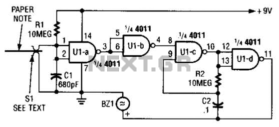
This device prevents paper notes and memos from being overlooked. A paper note placed between two fingers made of a conducting material (metal or conductive plastic) breaks the circuit, allowing pair 1 of Ul-a to go high. This causes...
This project is a 3 or more lines mixer. For more than 3 inputs you can repeat the input parts (P=10K R=22K). It powered with 9Vdc. The described project is a multi-channel audio mixer designed to handle three or more...

This is a circuit for an audio frequency meter. This circuit utilizes a 555 IC configured as a monostable multivibrator (one-shot trigger). A monostable multivibrator can function as a frequency-to-voltage converter by producing a fixed pulse width, with the...
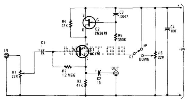
In this circuit, Q1 serves as a simple amplifier with gain control provided by a variable emitter resistance supplied by FET Q2. When switch SI is in the up position, capacitor C3 discharges through resistor R5, resulting in a...
The philosophy behind this minimalist design has been explained by Flavio Dellepiane on his highly interesting site. I have myself written an article about this fleapower amp from Italy in the American magazine AudioXpress. All relevant details are published...