
audio frequency meter

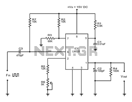
The audio frequency meter circuit is designed to measure frequencies within the audio range, typically from 20 Hz to 20 kHz. The core component, the 555 timer IC, is configured in a monostable mode, which allows it to produce a single output pulse each time it receives a triggering input. The duration of the output pulse is determined by the resistor (R1) and a capacitor (C1) connected to the timing circuit. The pulse width remains constant, while the frequency of the input signal dictates the rate at which the 555 timer is triggered.
In this configuration, the circuit operates as a frequency-to-voltage converter. As the frequency of the input audio signal increases, the rate of triggering increases, leading to a higher output voltage. This voltage can be easily measured using an ammeter. The selection of R1 is critical, as it defines the range of frequencies that can be measured. By incorporating a rotary switch, different resistor values can be selected, allowing for flexibility in measuring various frequency ranges.
The choice of ammeter is also significant. An analog ammeter provides a visual representation of the output voltage, but may not offer the precision required for all applications. A digital ammeter, particularly a dual-slope ADC, is recommended due to its ability to average readings over time, reducing fluctuations and providing a more stable output. While fast digital multimeters can also be utilized, their rapid sampling rates may introduce variability in readings, particularly in scenarios involving rapidly changing input frequencies.
Overall, this audio frequency meter circuit is a versatile tool for measuring audio frequencies, with the flexibility to adapt to different measurement ranges and the option to select between analog and digital readout methods. Proper selection of components and configurations will ensure accurate and reliable frequency measurements.This is a circui for audio frequency meter. This circuit uses 555 IC as a mono stable multi vibrator (one-shoot trigger). A mono stable multi vibrator can act as a frequency-to-voltage converter because it produces a fixed pulse width, with the repetition rate/density is proportional to the triggering input frequency. This is the figure of the cir cuit. For resistor R1, because it set the measurement range, it`s better to use a rotary switch to select different values for different ranges. For the ampere meter, you can use analog or digital ampere meter. A cheap dual-slope ADC digital meter is suitable because its averaging characteristic, but a fast digital multimeter can also be used although it may show some uncertainty because of their fast sampling.
🔗 External reference
Related Circuits
The LM331 is a precision voltage-to-frequency converter developed by National Semiconductors. This integrated circuit (IC) has various applications, including analog-to-digital conversion, long-term integration, voltage-to-frequency conversion, and frequency-to-voltage conversion. Its wide dynamic range and excellent linearity make it suitable for...
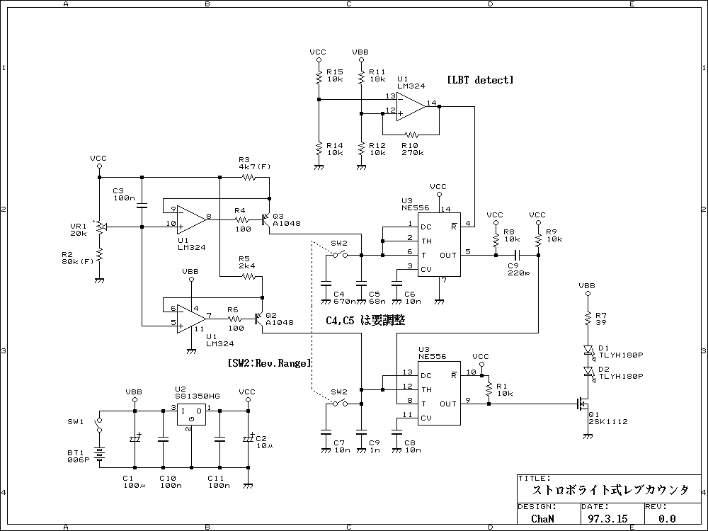
This is a simple rev-counter which can measure up to 100,000 rpm with method of strobe synchronization. Its usage is easy. Put a marker on the shaft before measuring, light on the shaft by flashing LED and adjust flashing...
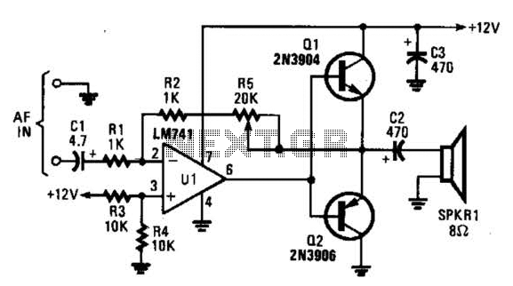
The circuit is designed around an LM741 operational amplifier configured as an inverting amplifier. It is utilized to drive complementary transistors (Q1 and Q2). The feedback loop of the op-amp incorporates the base-emitter junctions of both transistors, which aids...
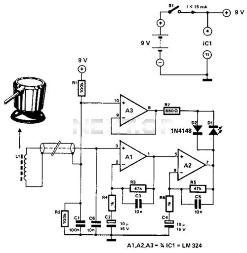
The circuit utilizes the principle that in an RL circuit, the pulse width across the inductor is proportional to the inductance. This circuit indirectly measures the inductance using a digital voltmeter (DVM). The measurement range is approximately 5 to...
This multimeter is designed to measure output voltage and current in a power supply unit (PSU), with the current sense shunt resistor connected in series with the load at the negative voltage rail. It operates using a single supply...
This circuit is designed for precise centigrade temperature measurement. It includes a transmitter section that converts the sensor's output voltage, which is proportional to the measured temperature, into frequency. The output frequency bursts are transmitted through the mains supply...