
Audio Mixer with 2N3819

This circuit functions as an audio mixer, designed to combine multiple audio signals into a single output channel. The basic configuration allows for the mixing of two channels, but the design is modular, permitting the addition of more input channels by replicating the input sections depicted in the schematic. Each input section typically comprises a potentiometer (R1, R3) and resistors (R2, R4, R5), which help to control the volume and balance of the individual channels being mixed.
The resistors used in the circuit include 10K potentiometers for adjusting the input levels, 100K resistors for signal conditioning, and a 6.8K resistor, which may serve as a part of the input impedance matching. The capacitors (C1, C2, C3) with a value of 0.1µF are included to filter out any DC components from the audio signals, ensuring that only the desired audio frequencies are passed through to the output.
The 2N3819 junction FET (Q1) acts as a low-noise amplifier, providing the necessary gain to the mixed signals while maintaining a high input impedance, which is critical in audio applications to avoid loading down the source signals.
For practical implementation, it is recommended to house the circuit in a shielded metal case to minimize electromagnetic interference and reduce the risk of oscillations, which can introduce unwanted noise into the audio signal. The output can be connected through a phono or other compatible plug, facilitating easy integration with various audio equipment. The circuit operates efficiently on a single 9-volt battery, making it suitable for portable applications where low power consumption is essential.This simple circuit mixes two or more channels into one channel (eg. stereo into mono). The circuit can mix as many or as few channels as you like and consumes very little power. The mixer is shown with two inputs, but you can add as many as you want by just duplicating the "sections" which are clearly visible on the schematic. R1, R3=10K Pot R2, R4=100K 1/4 W Resistor R5=6.8K 1/4 W Resistor C1, C2, C3=0.1uF Capacitor Q1=2N3819 Junction FET MISC=Wire, Shielded (Metal) Case, Phono Or Other Plug For Output Notes 1. As many or as few channels as are required can be added to the mixer. Do this by just duplicating the input "sections" which are clearly shown on the schematic. One version of this mixer I saw had 25 inputs! 2. A shielded case is probably needed to reduce hum and help stop oscillations. 3. The circuit can be powered by a single 9 volt battery. 🔗 External reference
Related Circuits
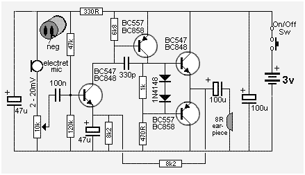
The following circuit presents a Mini Audio Amplifier Circuit Schematic Diagram. Features include a power consumption of less than 3mA, a small output, and the use of a push-pull configuration. The Mini Audio Amplifier Circuit is designed to amplify low-level...
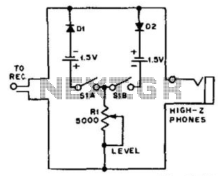
For use with headphones, this circuit sets the audio clipping level via a 5-kOhm potentiometer. This type of noise clipper is most effective for pulse-type noise with a low duty cycle, such as ignition noise. The resistor Rl establishes...

This car audio amplifier circuit is based on the LA47536 audio amplifier integrated circuit designed by Sanyo. This audio amplifier circuit is specifically designed for car audio power amplifiers. The LA47536 car audio amplifier IC features four output channels...
The circuit was designed to create an audio mixer that can be assembled in modules while providing 6 or more input channels. An audio mixer is a device used to combine multiple audio signals into a single output. The audio...
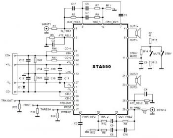
This is a stereo amplifier circuit diagram. The amplifier will produce stereo output channels with a power audio output that can reach up to 70W for each channel. The amplifier is built using the STA550 chip from STMicroelectronics. It...
The circuit of this 30W audio amplifier produces clear audio output quality. The circuit module does not have any improvements. It utilizes a Darlington pair in the transistor configuration. The 30W audio amplifier circuit is designed to deliver high-fidelity sound...