
30w Audio Amplifier Circuit

The 30W audio amplifier circuit is designed to deliver high-fidelity sound reproduction, suitable for various audio applications. The core of the amplifier is based on a Darlington pair configuration, which enhances the current gain and improves the overall efficiency of the amplifier. This configuration consists of two bipolar junction transistors (BJTs) connected together, where the emitter of the first transistor is connected to the base of the second. This arrangement allows for a significant increase in input impedance and a substantial reduction in the output impedance, making it ideal for driving speakers.
The circuit typically includes essential components such as resistors, capacitors, and power supply connections. A power supply providing an appropriate voltage level is critical for the amplifier's operation, as it directly affects the output power and quality. For a 30W output, the power supply voltage should be selected to ensure optimal performance without distortion.
The input stage of the amplifier may include a coupling capacitor to block any DC offset from the audio source, allowing only the AC audio signal to pass through. Feedback resistors can be implemented to stabilize the gain and improve linearity, thus enhancing the audio quality. Additionally, bypass capacitors are often used to filter out noise and provide a cleaner power supply to the amplifier circuit.
To ensure the reliability and longevity of the amplifier, proper heat dissipation techniques such as heat sinks or thermal pads may be employed, especially if the amplifier is expected to operate at high output levels for extended periods.
Overall, the 30W audio amplifier circuit is a straightforward yet effective design that leverages the advantages of a Darlington pair to achieve clear audio output, making it suitable for various audio applications.The circuit of this 30W audio amplifier produce a clear audio output quality. The circuit module doesn`t have any improvement. With Darlington pair in tra. [read more] 🔗 External reference
Related Circuits
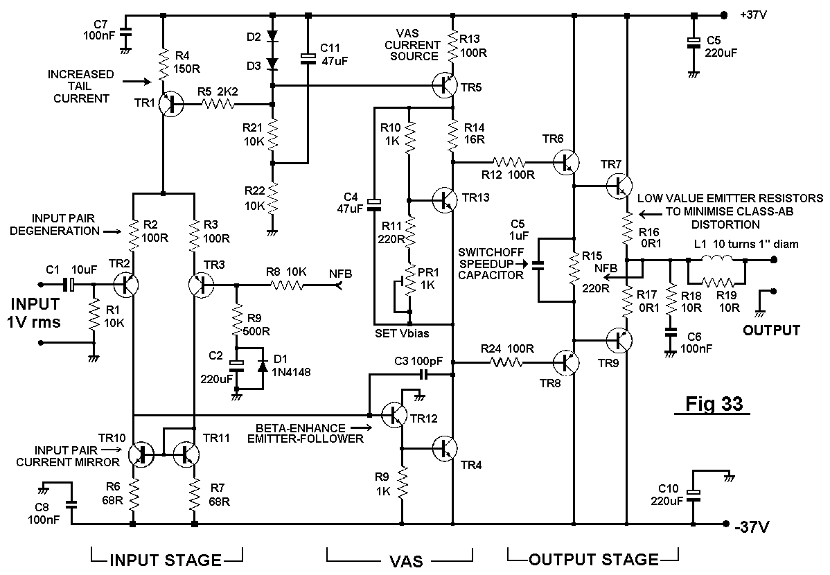
The distortion produced by a typical solid-state Class-B power amplifier consists of eight mechanisms, all of which may coexist and whose distortion products overlap to create a complex result. Methods for isolating each mechanism for study and minimizing its...
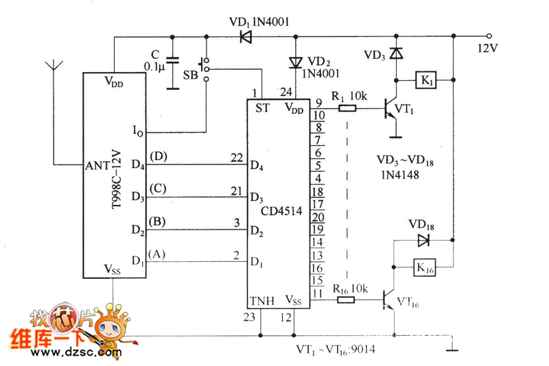
The circuit functions as both a latch output and a non-latched output. The control switch, labeled SB, governs the operation. When both SB and VDD are activated, the circuit enters the latch output state, allowing the sixteen output terminals...
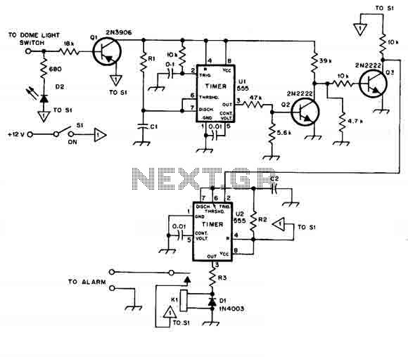
When this car alarm circuit is activated, it remains active for 80 seconds. There is a 15-second delay for the driver to enter and deactivate the alarm. All timings can be easily modified. The circuit utilizes two NE555 timers,...
A conventional digital home theater amplifier necessitates a dedicated integrated circuit, which is often produced by a limited number of manufacturers, resulting in higher costs. This circuit element can be produced using standard components, delivering a power output of...
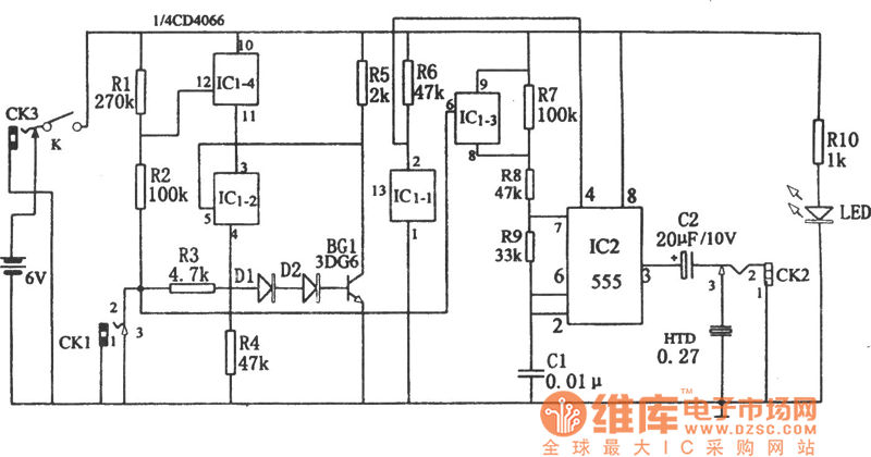
The circuit diagram illustrates a five-use tri-state audio logic pen utilizing components such as the CD4066 and a 555 timer. The primary elements include a multivibrator, a four-way switch (CD4066, designated as IC1), and a gate circuit formed by...
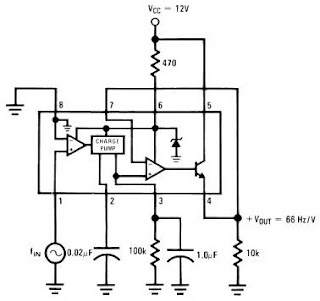
The LM2917 IC chip is specifically designed as a Frequency to Voltage Converter. It requires only a few external components for its operation. The datasheet for the LM2917 IC includes several application examples of the Frequency to Voltage Converter....