
Audio Monitoring System

The schematic of this broadcast monitoring system comprises several interconnected components that work together to achieve efficient audio monitoring and fault detection. The demodulator serves as the primary interface for receiving broadcast signals, which can be either digital radio or television. This device converts the modulated signals into a format suitable for audio processing.
The audio amplifier is connected to the demodulator's output, enhancing the signal strength to ensure clear audio playback. The amplifier's output is routed to both a speaker and an LED indicator system. The LEDs provide visual alerts corresponding to audio presence, assisting operators in quickly identifying audio issues.
The programmable device acts as the system's control unit, managing the automatic switching of channels or frequencies every 10 seconds. This function is crucial for monitoring non-critical programs, as it allows the system to scan through various broadcasts and identify any faults or quality issues. The device is programmed with specific parameters to determine when to switch channels, based on audio quality metrics.
A feedback loop is established between the audio output and the monitoring interface, which includes both visual and audio indicators. This loop enables real-time assessment of audio quality, allowing for immediate detection of faults. The audio alarm indicators are particularly useful, as they provide audible notifications when audio signals are absent or degrade below a predefined quality threshold.
In summary, the described system integrates multiple components to facilitate comprehensive broadcast monitoring. The combination of a demodulator, audio amplifier, programmable control unit, and monitoring indicators creates a robust framework for ensuring audio quality and timely fault detection in broadcast environments. As shown in Figure Block Diagram for the system. Important Important programs for broadcast monitoring period, using the selected demodulator, can be displayed by the presence or absence of audio, audio amplifier friendly interface to monitor and listen in order to ensure timely and accurate detect faults and ensure the quality of audio ; to monitor non-critical programs, automatic switching channels (or frequency) demodulator + audio + LED monitor monitor audio alerts. By a single chip programmable device, programming. Automatic control demodulator (digital radio or television) to automatically change the channel about every 10s.
According to monitoring by both the screen display and corresponding sound judgment set aside quality, it can also be audio and audio alarm indicator largely determine the presence or absence of audio.
Related Circuits

A solar-powered watering system has been proposed to irrigate plants daily using water collected in butts located by the greenhouse. This project has been under development for a considerable time and is now being revisited with the aim of...
The circuit described is a metal detector. The operation of the circuit is based on the superheterodyne principle, which is commonly used in superheterodyne receivers. The circuit utilizes two RF oscillators, both fixed at a frequency of 5.5 MHz....
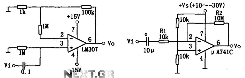
The simple audio amplifier circuit is illustrated in the figure. Utilizing an integrated op-amp configuration, this audio amplifier is stable and allows for easy negative feedback, facilitating the achievement of equalization characteristics. Additionally, the crosstalk between channels is minimal,...
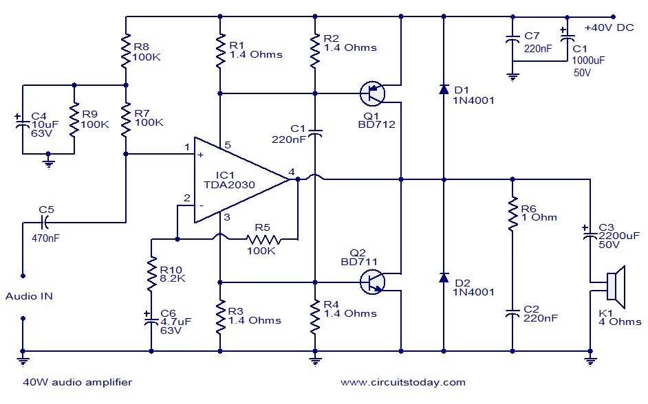
This is a highly effective 40W power amplifier design utilizing the TDA2030 integrated circuit and two transistors. The circuit consists of only a few components and does not necessitate a dual power supply. The input signal is connected to...
The following circuit diagram represents a simplified application circuit of the TDA8932B/33(B) device when operated from an asymmetrical (single) supply. To streamline the design for an asymmetrical supply in a single-ended (SE) configuration, the TDA8932B/33(B) incorporates three integrated half-supply...
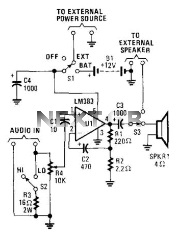
This audio power amplifier, built around an LM383 8-W audio power amplifier, is designed to enhance an audio signal to a sufficient level for audibility in high-noise environments. It is important to note that the LM383 requires a heatsink...