
Simple audio amplifier LM307 A741

This audio amplifier circuit is designed for versatility and efficiency in audio signal processing. The dual power supply configuration in Figure (a) allows for a stable operation with the LM307N op-amp, which is well-suited for audio applications due to its low noise and high gain characteristics. The use of a coupling capacitor (0.1 µF) ensures that only the AC components of the audio signal are amplified, while blocking any DC offset that could affect performance.
In contrast, the single power supply configuration in Figure (b) simplifies the power requirements, making it suitable for battery-operated devices. The design effectively manages the DC offset through the implementation of negative feedback, ensuring that the amplifier maintains a linear response across the audio frequency range. The choice of feedback components (R1 and R2) is crucial, as they define the gain and frequency response of the amplifier. The gain equation highlights the inverse relationship between R1 and R2, allowing for precise control over amplification levels.
Moreover, the low-frequency characteristics of the circuit can be tailored by adjusting the values of R1, R2, and the coupling capacitor C, which can be particularly beneficial in applications requiring specific equalization or filtering of audio signals. The design also minimizes crosstalk, enhancing the quality of mixed audio inputs and ensuring a clearer output.
Overall, this simple audio amplifier circuit is a robust solution for various audio applications, providing stable amplification with minimal interference and the flexibility to accommodate different signal conditions. As shown in FIG simple audio amplifier circuit. Using the integrated op-amp configuration of audio amplifier is stable, easy to negative feedback, so it is easy to get equaliza tion characteristics. In addition, crosstalk between channels is small, it is also very easy to mix multiple input channels. Figure (a) shows a circuit using a dual power supply (Vs 15V), with the phase-inverting input terminal, respectively, to ground the static balance resistance, the input signal Vi by the 0.1 F coupling capacitor into LM307N-inverting input terminal (Cited 3 feet).
The signal source, the input resistance of about 1M, and therefore the equivalent load is light. The circuit voltage is about 101 times magnification, and has good dynamic characteristics. Figure (b) shows a circuit using a single power supply, because the DC level signal problem does not exist in the AC amplifier, so this power supply is desirable. In this circuit, the audio signal via a coupling capacitor C K and resistor R1 fed, A741C inverting input (pin 2).
The figure shows that the circuit for DC component is introduced 100% negative feedback (c DC component is quite open), so the offset voltage without amplification. The voltage of the circuit magnification: Av -R2/R1 -1000 (ie 60dB). It should be emphasized that: R1, R2 and capacitor C having low frequency attenuation and phase shift effect, when the signal frequency is low, may be appropriate to increase the capacitance C of capacity.
Related Circuits
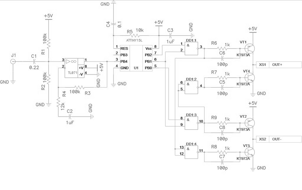
Class D amplifier circuit diagram for the ATtiny15L microcontroller. This document introduces a specific implementation of a Class D amplifier. The ATtiny15L from Atmel's AVR family is ideal for this application due to its integrated ten-bit analog-to-digital converter (ADC)...
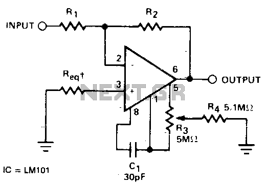
The required resistance (Req) may be zero or equal to the parallel combination of resistors R1 and R2 to achieve minimum offset. The circuit configuration described involves the use of two resistors, R1 and R2, connected in parallel. In a...
Nice small audio amplifier which use only few parts to give good quality sound. This amp can be used as a simple booster, the heart of a more complicated amplifier or used as a guitar amp. Although not perfect,...
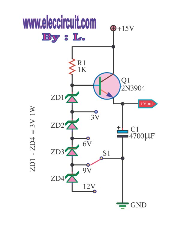
This is a DC regulator circuit that can provide multiple output voltages simply. It functions as a simple step-down DC converter and is designed with a fixed resistor R1. The described circuit operates as a DC voltage regulator, specifically designed...
The limitation of this architecture is that it overlooks the variations among different channels. Initially, the subwoofer channel has a limited bandwidth, and its signal is often produced in real-time by summing the low-frequency components from the full-bandwidth channels....
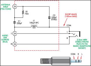
This document presents a concept for a low-cost adapter that enables the connection of a portable FM radio or MP3 player with an FM tuner to an external antenna and audio equipment, such as a hi-fi system or PC...