
Audio Noise Filter Circuit

The audio noise filter circuit operates as a bandpass filter, which allows signals within a specific frequency range to pass while attenuating frequencies outside this range. Typically, the audio frequency band extends from 20 Hz to 20 kHz, which corresponds to the range of human hearing.
The circuit can be constructed using passive components such as resistors, capacitors, and inductors, or it can be implemented using active components such as operational amplifiers to improve performance. In a passive bandpass filter configuration, a combination of low-pass and high-pass filters is used. The low-pass filter attenuates frequencies above the desired range, while the high-pass filter attenuates frequencies below the desired range.
For example, if the target frequency range is from 100 Hz to 10 kHz, the low-pass filter can be designed with a cutoff frequency of 10 kHz, and the high-pass filter can be designed with a cutoff frequency of 100 Hz. The design of the filter can be calculated using standard filter design equations, considering the desired gain, bandwidth, and quality factor (Q).
In an active configuration, operational amplifiers can be utilized to create a more selective and stable bandpass filter. This configuration allows for greater control over gain and impedance matching, making it suitable for various audio applications. The circuit may also incorporate feedback mechanisms to enhance the filter's performance, reduce distortion, and improve signal-to-noise ratio.
Overall, the audio noise filter circuit is essential in audio processing systems, ensuring that only the desired audio signals are amplified and transmitted, thereby improving the overall sound quality.This audio noise filter circuit is a bandpass filter for audio frequency band. It filters unwanted signals that are lower or higher than the audio frequenc.. 🔗 External reference
Related Circuits
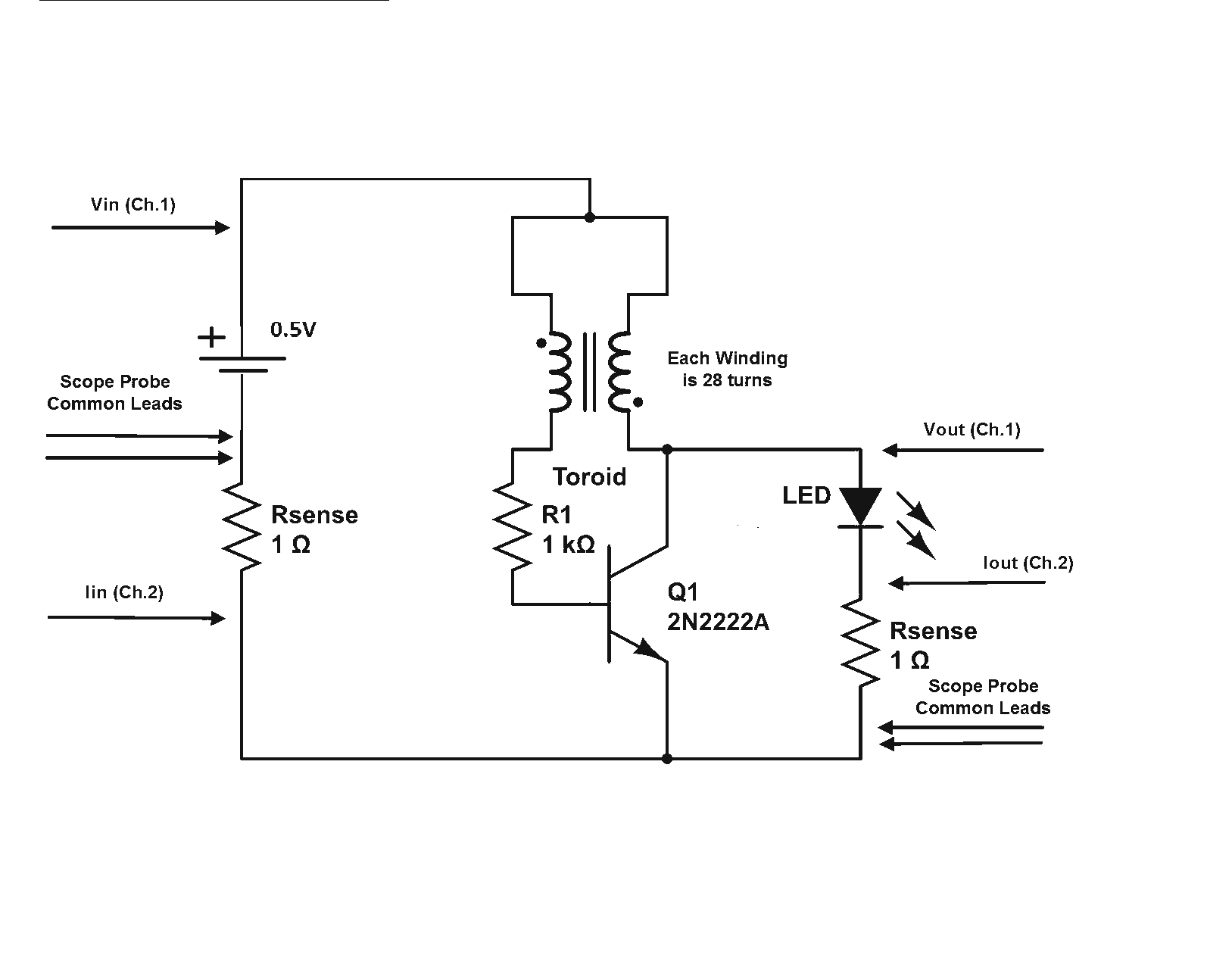
Is a Joule Thief circuit capable of achieving overunity? Joule Thief schematic including scope measurement points. The Joule Thief is a minimalist circuit designed to extract energy from low-voltage sources, such as depleted batteries, and convert it into a usable...
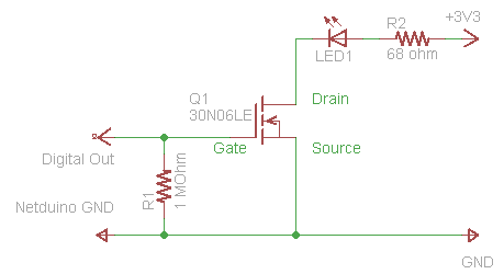
The process of driving an LED involves using a Power MOSFET to control the LED's state (On and Off) via a digital signal. This guide provides a step-by-step approach to wiring the circuit on a breadboard, which serves as...

This is an economical FM booster circuit designed to enhance the reception of distant FM stations on local radios. The circuit diagram features a common-emitter tuned RF preamplifier utilizing the VHF/UHF transistor 2SC2570. The circuit's output should be directly...
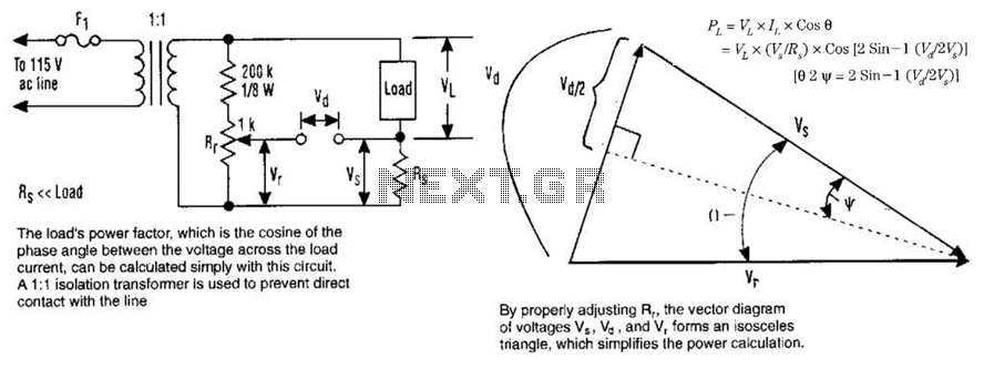
The load's power factor, defined as the cosine of the phase angle between the voltage across the load and the load current, can be calculated using this circuit. An isolation transformer with a 1:1 ratio is employed to prevent...
A voltage supply ranging from 6 V to 15 V is required when using a single LED per module. An increase in the number of LEDs necessitates a corresponding increase in the voltage supply, with additional LEDs connected in...
A car inverter, also known as a power converter or power inverter, is a device that converts 12V DC from a vehicle’s electrical system into 220V AC for general electrical use. It serves as a convenient power adapter for...