
FM Booster Circuit PCB

The FM booster circuit is designed to improve the signal strength of FM broadcasts, particularly for stations that are not easily accessible due to distance or obstructions. The use of a common-emitter configuration in the RF preamplifier stage allows for significant amplification of weak signals while maintaining a suitable level of noise. The 2SC2570 transistor is chosen for its high frequency response and low noise characteristics, making it ideal for VHF/UHF applications.
The assembly of the circuit on a quality printed circuit board (PCB) is crucial for minimizing interference and ensuring stable operation. Care should be taken to properly solder all connections, and components should be placed to minimize parasitic capacitances and inductances. The trimmer capacitors in the circuit allow for fine-tuning of the resonant frequency of the input stage, optimizing the circuit's performance for specific FM frequencies.
The input coil L1, made of 20 SWG enameled copper wire, is wound with four turns to create an inductive element that, in conjunction with the tuning capacitors, forms a resonant circuit. The spacing of the turns is important to reduce coupling losses and improve the quality factor (Q) of the coil. The 5mm diameter former provides a stable structure for the coil, ensuring consistent performance.
In summary, this FM booster circuit is an effective solution for enhancing FM reception capabilities, allowing users to enjoy clearer audio from distant stations. Proper assembly, tuning, and component selection are essential for achieving the best results.This is a low cost FM booster circuit to receive far away fm stations clearly on your radio in your local area. The circuit diagram of FM booster consist of a common-emitter tuned RF preamplifier wired around VHF/UHF transistor 2SC2570.
The output of the circuit should be directly connected to your FM receiver. Assemble the circuit on a good quali ty PCB and adjust the trimmers to get maxim gain. Input coil L1 consists of four turns of 20SWG enameled copper wire (slightly space wound) over 5mm diameter former. The pin configuration of the transistor can also found on the circuit diagram. 🔗 External reference
Related Circuits
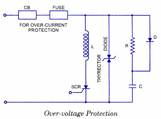
Silicon Controlled Rectifiers (SCRs) are sensitive to high voltage, over-current, and transients. To ensure satisfactory and reliable operation, they must be protected against such abnormal operating conditions. Due to the complexity and cost of protection mechanisms, devices with ratings...
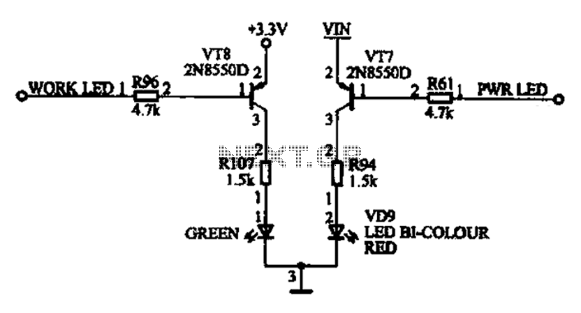
The ACER PM02 MP4 machine features a voltage status indicator circuit. When power is supplied, a red LED illuminates, indicating that the device is powered on. Upon entering operational mode, a green LED lights up. The voltage status indicator circuit...
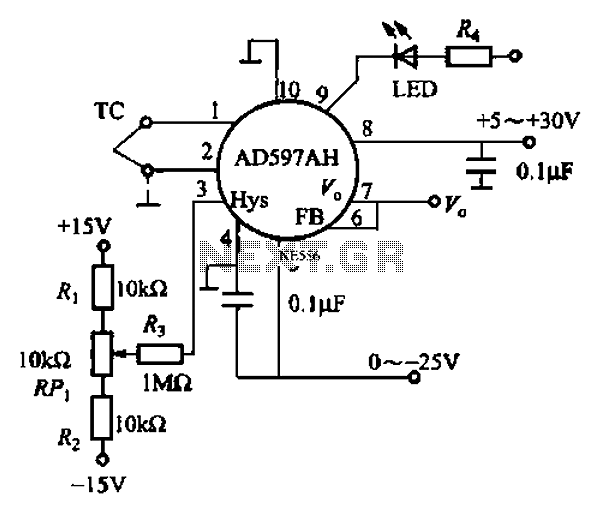
An automatic electric furnace temperature controller is illustrated. The closed circuit consists of a temperature detection output control loop; as the temperature increases, the output voltage rises until it reaches a preset temperature value, at which point the output...
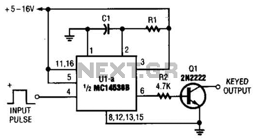
With switch SI in the off position, battery voltage is applied across timing capacitor CI, which remains charged while the rest of the circuitry is powered off. Transistor Q1, and consequently transistors Q2 through Q4, remain in an off...
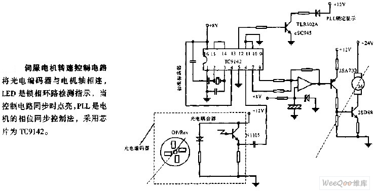
The servo motor speed control circuit connects the photoelectric encoder to the motor shaft. The LED serves as an indicator light for the phase-locked loop (PLL) detection, illuminating when the control circuit is synchronized. The PLL employs a phase...

Any number of normally-open switches may be utilized. Install "tilt" switches that close when the steering is moved or when the bike is lifted off its side-stand or pushed forward off its centre-stand. Employ micro-switches to secure removable panels...